User Manual X8400 sc
14
General
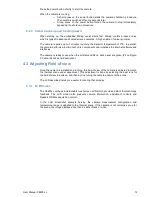
When detached, the LCD screen can be connected to the camera using a provided right
angled USB extender cable. Any additional USB extender cable can be added to extend the
length. Performances are then strongly depending on the quality of the used cable and the
environment in which the camera is used.
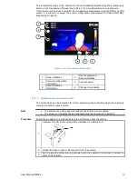
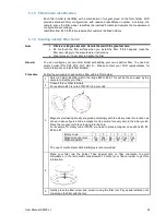
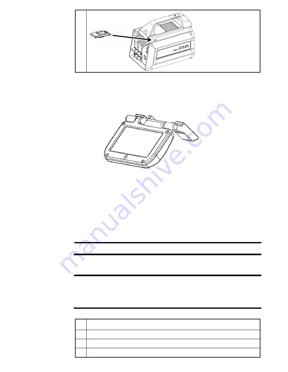
The screen has been designed to be easily used on a workbench, as shown in next figure
The screen detects automatically its orientation and flips the interface accordingly. The
orientation can be locked in the ResearchIR Max camera user interface (see §4.4.8)
4.3.2 Lens
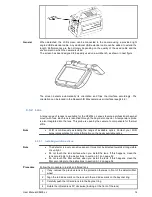
A large range of lenses is available for the X8400sc. Lenses feature a professional bayonet
mount with lock. Each lens is identified through the bayonet connector. A temperature probe
is also integrated into the lens. This probe is used by the camera to compensate for thermal
drifts.
Note
•
FLIR is continuously extending the range of available optics. Contact your FLIR
sales representative for more information on the newly available optics.
Installing an infrared lens
4.3.2.1
Note
•
The detector is a very sensitive sensor. It must not be directed towards strong visible
or sun light.
•
Do not touch the lens surface when you install the lens. If this happens, clean the
lens accordingly to the instructions in section 9.1.2 on page 52.
•
Do not touch the filter surface when you install the lens. If this happens, clean the
filter accordingly to the instructions in section 9.1.2 on page 52
Procedure
Follow the procedure to install an infrared lens
1
If any, remove the previous lens or the protection that was in front of the detector/filter
wheel
2
Align the red index mark on the lens with the red index mark on the bayonet ring
3
Carefully push the infrared lens into the bayonet ring
4
Rotate the infrared lens 30° clockwise (looking a t the front of the lens)


