14
GB
O R I G I N A L I N S T R U C T I O N S
Check that no part of the product has been damaged during transport. In case of damage detection, such as cracks or deforma-
tions, it will disqualify the product from further use until it is repaired or damaged components are replaced.
It is recommended to place the components on a
fl
at, hard, and clean surface.
Use personal protective equipment such as protective gloves, eye protection, and protective clothing during assembly.
Caution! Make sure that the tool is not connected to the power supply before starting the assembly
.
The power supply
cord plug must be removed from the socket
.
Tool assembly
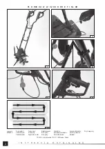
Set the tool on the ground so that the blades face downwards.
Install the handles so that the tool looks as in Figure (I). Slide the lower parts of the handles into the sockets in the motor housing
and secure them with screws (II). Secure the connections of the upper part of the handles using screws and knobs (iii). The screws
have square heads which must be adjusted to the holes in the handle pipes. Screw the knobs on the inside of the handles. Such
installation will reduce the risk of accidental catching of the knobs on an obstacle during operation. The cables connecting the
switch to the motor should be
fi
xed to the handle pipes with the supplied clips (III). If they are allowed to hang loose, they can
become entangled with an obstacle, tool or the operator, increasing the risk of injury and electric shock.
When assembled in this manner, the tool is ready to work.
Preparing the workplace
The tiller is intended only for soil cultivation. The ground cannot be too hard. If the ground is too hard or dry, moisturise it before
starting work and wait for the water to soak into the ground.
Working on a hard surface such as concrete or wood is prohibited.
Before starting work, remove all visible stones, roots, wires and other items which may damage the tiller blades. Particular atten-
tion should be paid to electrical cables, including those supplying power to the tool. Be aware that electrical cables can be hidden
underground.
The tiller only works correctly when it is driven forward. Avoid reversing the tool. During reversing, the power supply cord can be
caught and cut, which can cause electric shock.
The workplace and length of the power supply cord must be prepared and adjusted in such a manner that it is possible to move
along rows (VII). Rows should be kept equal in width, slightly overlapping so as not to leave any space. Take special care when
changing the direction. Make sure to begin work from the electrical connection side. This will reduce the risk of driving over the
power supply cord.
Connecting to the power supply
The tool is equipped only with a short power supply cord and it is necessary to use extension cords. Always use cords intended
for outdoor use due to the nature of the work. The power supply cord should have a single socket matching the tool’s plug. It is
forbidden to modify the plug or socket to make them
fi
t. The electrical parameters of the power supply cord should correspond to
the electrical parameters of the tool, listed on the rating plate. It should be noted that the size of the power supply cord’s gauge
depends on the length of the cord. Follow the instructions below regarding the power supply cord gauge:
- 1.0 mm
2
– cord length not greater than 40 m;
- 1.5 mm
2
– cord length not greater than 60 m;
- 2.5 mm
2
– cord length not greater than 100 m.
When preparing for operation and during operation, pay attention to the power supply cord. Protect the power supply cord from
water, moisture, oils, heat sources and sharp objects. Lay the cord so that it does not come within the reach of the tool’s blade.
Cutting the cord may result in electric shock and serious injury or death. Make sure that you do not become entangled in the cord.
This can lead to a fall and serious injury.
Do not overload the power supply cord, and do not cause any of the cord’s section to become stressed. Do not pull the cord
when moving the tool. Always remove the cord plug and socket by pulling on the plug and socket housing, never pull on the cord.
Pass the extension cord through the hole in the tool handle and attach it to the hook (V). This will protect the plug of the cord and
extension cord from being pulled out.
Starting the tool
Set the tiller in the place where the work is to commence. The tiller can only be started when in vertical position.
If the tiller is equipped with supporting wheels, rest it on the wheels and lift the blades so that they do not come into contact with
the ground. If the tiller does not have supporting wheels, set the blades on the ground. Grasp both handles
fi
rmly.
The switch is equipped with a safety device, protecting against starting the tool accidentally. To start the tool, press and hold the
lock button with your thumb, then press and hold the switch. The tool will start and the blades will begin spinning. You do not need
to hold down the lock button any longer, but hold down the switch at all times. The switch cannot be locked in the “on” position.
The tool stops when the pressure on the switch is released.
The blades may still rotate for some time after releasing the pressure on the switch.
When work is
fi
nished, turn o
ff
the tool, wait for the blades to stop completely, disconnect it by removing the plug from the power
supply socket and proceed with maintenance.
Summary of Contents for 79725
Page 22: ...22 RUS II 30...
Page 23: ...23 RUS I II III III VII...
Page 24: ...24 RUS 1 0 2 40 1 5 2 60 2 5 2 100 V 3 4 VII...
Page 25: ...25 RUS 0 3 50 10 30...
Page 27: ...27 UA II 30...
Page 28: ...28 UA I II III III VII 1 0 2 40 1 5 2 60 2 5 2 100...
Page 29: ...29 UA V 3 4 VII 0 3...
Page 30: ...30 UA 50 10 30 C...
Page 78: ...78 GR RCD 30 mA...
Page 79: ...79 GR I II III III VII 1 0 mm2 40 m 1 5 mm2 60 m...
Page 80: ...80 GR 2 5 mm2 100 m V 3 4 VII 0 3 Mpa...
Page 81: ...81 GR 50 10 30 C...


