background image


27 

Notes:


Summary of Contents for EGM Series

Page 1: ...EGM Series Oval Gear Flow meters Operation Manual Version 18 16 ...

Page 2: ... only be installed and maintained by persons familiar with local regulations particularly those for workplace Health and Safety For best results please make yourself familiar with the contents of all relevant product manuals prior to installation and commissioning If further assistance is required please consult the distributor from whom you purchased your flow meter Your flow meter and any associ...

Page 3: ...nt 13 4 Electrical Installation 14 4 1 Wiring 14 4 2 Hall Effect Outputs 15 4 3 RTD Output PT100 16 4 4 Wiring Diagrams 17 4 4 1 Standard Pulse Output Board 17 4 4 2 Fuel Consumption Option 17 4 4 3 Fuel Consumption Wiring with F127 Flow Computer 18 4 5 Meter Calibration Factor K Factor Scale Factor 18 5 Commissioning 19 6 Maintenance 20 6 1 Parts Identification 21 6 2 Flowmeter Disassembly 22 6 3...

Page 4: ...ch as a PLC or DCS The cable output from the flow meter can also be wired to instruments such as totalisers rate totalisers or batch controllers These instruments are available from your Flomec distributor and can be purchased with monitoring and control output options including 4 20mA scaled pulse flow rate alarms and batch control logic preset metering 1 1 Operating Principle Oval Gear flow mete...

Page 5: ...0 1 6 145 3 500cP 0 25 27 0 07 7 1 0 5 100 0 13 26 4 2 550 0 53 145 3 1000cP 2 0 12 16 0 03 4 2 0 3 45 0 08 11 9 1 5 360 0 40 95 1 Nominal Output Pulse Resolution Pulses Litre Pulses USGallon Standard Hall Effect 2800 10600 1060 4012 720 2725 Fuel Consumption Option 2800 10600 1060 4012 180 681 Minimum Filtration 75 micron 200 mesh 3 Notes 1 When operating on 1cP liquids the meters may be used up ...

Page 6: ... 3 40 0 08 10 57 1 5 80 0 40 21 1 1000cP 2 0 2 25 0 05 6 60 1 50 0 26 13 2 Nominal Output Pulse Resolution Pulses Litre Pulses USGallon Standard Hall Effect 170 644 105 398 Fuel Consumption Option 42 5 161 26 3 99 5 Minimum Filtration 75 micron 200 mesh 3 Notes 4 When operating on 1cP liquids the meters may be used up to the nominal 3cP maximum flow rate rating for intermittent periods only 5 For ...

Page 7: ...Current 10mA Maximum Fuel Consumption Option Hall Effect Output Output Type NPN Open Collector Voltage Range 5 24VDC Current Draw 20mA Maximum Switching Current 10mA Maximum RTD Output Sensor Type Platinum Resistance According to IEC 60751 Nominal Resistance 100 Ohm Temperature Coefficient 3850 ppm K Tolerance Class F0 3 Class B Maximum Measurement Current 0 1mA 1 0mA ...

Page 8: ...stributor prior to installation That the system pressure and temperature are within the limits shown on the flow meter name plate That the maximum and minimum flow rates are within the specification of the flow meter That the liquid being metered is free of any particles That the meter is not exposed to temperatures system or ambient that may cause the liquid to flash convert to a gas within the f...

Page 9: ... For those users that wish to carry out pre installation testing or calibration of a non calibrated model it is important that the test procedure be carried out scientifically or the results of the test will be meaningless Particular cases that may benefit from field calibration or accuracy testing are those with liquids of very low viscosity 1cP For any field calibration of your flow meter it is ...

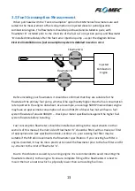
Page 10: ...system upstream of the meter must be fitted with a surge suppressor or pressure relief valve to protect the meter from damage High frequency flow pulsations will create erroneous readings and in extreme cases may damage the meter most pulsations are removed with the installation of a suitable pulsation dampener 3 1 Installation Orientation Almost all positive displacement flowmeters have a specifi...

Page 11: ...not operate a flow meter directly discharging to atmosphere Piping should be designed so that the flow meter is full of liquid at all times this is achieved by designing the inlet and outlet piping for the flow meter to be lower than all surrounding piping For vertical installations the liquid should travel from bottom to top i e it should rise vertically through the flow meter This will ensure th...

Page 12: ...etal particles from cutting or welding on new or modified installations It is always advisable to fit the inlet side of any Oval Gear flow meter directly to a strainer of appropriate pipe size and mesh size to suit the liquid being measured The minimum mesh size as shown in the specifications section of this manual should be adhered to where ever possible When metering medium or high viscosity flu...

Page 13: ...n approximate consumption of around 50L Hr of diesel fuel but will have a fuel system flowrate of around 300L Hr check your meter specifications against the higher fuel system flowrate before installing Fuel consumption flowmeters should be installed according to the requirements in other sections of this manual the inlet side of Flowmeter A should be fitted with a strainer or filter of appropriat...

Page 14: ...nput terminals of a receiving instrument or control system For installations which require a longer length of cable than is provided from the factory 2 metres an in line connector kit and extra lengths of cable can be purchased from your Flomec distributor Alternatively any good quality in line connector with a suitable number of pins and a suitable IP rating can be used For standard pulse output ...

Page 15: ... a reliable output type producing a consistent output irrespective of supply voltage variations below the maximum voltage limit temperature variations or mechanical shock The service life of the Hall Effect output is theoretically infinite so long as it is protected from high energy voltage spikes Hall Effect outputs are protected against reverse polarity and against low energy voltage spikes howe...

Page 16: ...en using the RTD in a 3 wire system the third wire is used to calculate the average resistance of the cable between the readout instrument and the RTD this allows the readout instrument to subtract the resistance of the cable from the resistance of the RTD itself giving a much more accurate measurement The downsides of a 3 wire system is a small amount of extra cost For installations which cannot ...

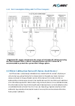
Page 17: ... the receiving instrument unless the instrument has an integral pull up 4 4 2 Fuel Consumption Option A Pull Up Resistor must be installed between the signal and VDC connections on the receiving instrument unless the instrument has an integral pull up For installations using 2 wire RTD PT100 connections use only the yellow green wires ...

Page 18: ...re which is characteristic to the particular meter Nominal values are shown in the specification section of this manual For meters ordered un calibrated the nominal values shown in the specification section should be used additional error should be expected for meters when using nominal K factors on un calibrated meters this information can be found in the Specification Table section 1 2 Field cal...

Page 19: ...long periods of time Do not start up your system for the first time by opening all valves and turning on the pump or by quickly opening up the supply valve from a gravity feed tank it is essential that the system is first purged of air Large volumes of air contained in the piping will be compressed very quickly between the oncoming liquid and the stationary flow meter rotors and will spin the roto...

Page 20: ...spection regime should be used Frequency of maintenance depends on the operational conditions of the meter and the criticality of the system it is the user s responsibility to determine inspection frequency however the manufacturer can provide guidance For any installations that require in situ cleaning CIP it is important that the cleaning or flushing procedures do not produce operating condition...

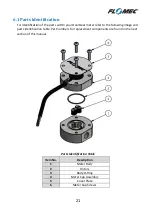
Page 21: ...ter refer to the following image and parts identification table Part numbers for replacement components are found in the next section of this manual Parts Identification Table Item No Description 1 Meter Body 2 Rotors 3 Body O Ring 4 Meter Cap Assembly 5 Cover Plate 6 Meter Cap Screws ...

Page 22: ... on any part of the meter body Take care of the thrust face of the bearings which protrudes from each end face of the rotors by a very small amount 6 4 Re assembly of Flowmeter When re installing the rotors the magnets MUST be correctly positioned so that they are facing the sensor located in the meter cap the magnets are inserted from the underside of the rotor so will not be visible when the rot...

Page 23: ... body assembly 1401209 1401213 1401217 Rotor Kit SS Rotors with Bronze bushings suits STD PCB 1524152 1524153 1524154 SS Rotors with Bronze bushings suits FC PCB 1524156 1524157 1524158 SS Rotors with Carbon bushings suits STD PCB 1524038 1524006 1524007 SS Rotors with Carbon bushings suits FC PCB 1524023 1524024 1524025 PPS Rotors suits STD PCB 1524063 PPS Rotors suits FC PCB 1524080 Meter Cap in...

Page 24: ...arbon bushings suits STD PCB 1524022 SS Rotors with Carbon bushings suits FC PCB 1524027 PPS Rotors suits STD PCB 1524049 1524160 PPS Rotors suits FC PCB 1524082 1524161 Meter Cap inc PCB Aluminium cap assembly with Standard PCB 1402202 Aluminium cap assembly with Fuel Consumption PCB 1402208 Stainless Steel cap assembly with Standard PCB 1402203 Stainless Steel cap assembly with Fuel Consumption ...

Page 25: ...ng tape or compound rust etc Step 3 Ensure flow is present No flow or lower than normal minimum flow may be attributed to a blocked strainer jammed or damaged rotors within the flowmeter malfunctioning pump closed valves or low liquid level in feeder tank Step 4 Ensure oval gears within meter are rotating Rotation of the oval gears can be heard by holding a screw driver blade to the meter body and...

Page 26: ...utput signal interference Confirm correct wiring with shielded cable Check all electrical connections for firmness and continuity No Output from Flowmeter Rotors jammed If meter has been recently field serviced check that rotors are not installed upside down or incorrectly meshed Check for obstruction due to foreign particles Clean repair or replace rotors Meter incorrectly reassembled See instruc...

Page 27: ...27 Notes ...

Page 28: ...28 EGM Series Operation Manual IM EGM 1816 ...

Reviews: