14
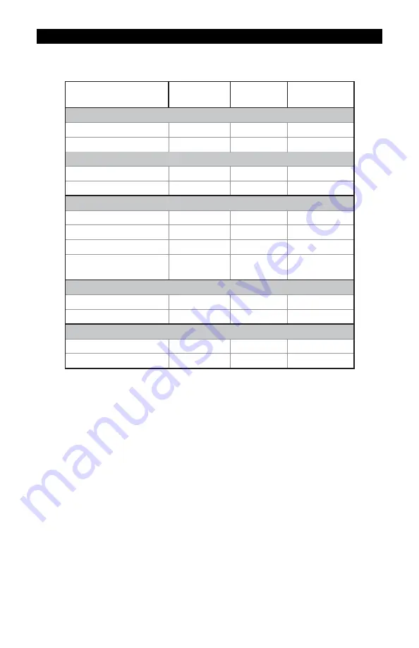
SPECIFICATIONS – ANSI FLANGE FITTINGS
All data on Model 1 inch determined with 1 centipoise solvent test fluid at 70° F (21°
C). Data on Models 1-1/2 inch and 2 inch is determined with water at 70° F (21° C).
Model Size
S10F
1 in.
S15F
1
‑‑‑‑
1/2 in.
S20F
2 in.
Linear Flow Range
Gallons/minute (GPM)
5-50
10-100
20-200
Litres/minute (LPM)
18.9-190
38-380
76-760
Maximum Flow
1
Gallons/minute (GPM)
75
150
300
Litres/minute (LPM)
284
568
1,136
Maximum Pressure Drop
in 10:1 Range
PSIG
10
4
7
bar
0.69
0.28
0.48
Frequency Range in
Linear Flow Range
47-470 Hz
36-360 Hz
33-330 Hz
Connections
ANSI 150 lb. Flange
Yes
Yes
Yes
Bolt Size
1/2 in.
1/2 in.
5/8 in.
Weight*
Pounds
5.7 lbs.
10.2 lbs.
16.7 lbs.
Kilograms
2.6 kg
4.6 kg
7.6 kg
* Computer electronics add 0.2 lbs. (0.1kg) to total weight.
1
The meter can operate up to this flowrate without damage. Continuous
operation will severely degrade meter life and performance.
Performance
Linear Range for 1 in.:
10:1 @ ±1.5% of reading
Linear Range for 1-1/2 in. and 2 in.:
10:1 @ ±1.0% of reading
Repeatability:
±0.1%
Pressure Rating
Flange Rule
Wetted Components
Housing:
316 Stainless Steel
Journal Bearings:
Ceramic (96% Alumina)
Shaft:
Tungsten Carbide
Rotor and Supports:
PVDF
Retaining Rings:
316 Stainless Steel
Temperature Range
-40° F to +250° F (-40° C to +121° C)
These temperatures apply to operations and storage. They are only for the
turbine without computer electronics. Final operational temperature range is
determined by computer electronics or accessory modules.
Summary of Contents for G2
Page 23: ...23 NOTES ...


