Installation 9
2.4 Meters fitted with integral Instruments
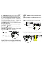
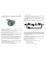
If your flowmeter is fitted with an integral instrument such as a
totaliser, rate totaliser or batch controller then the pulse output from the meter has been factory wired to the flow
input of the readout instrument.
As a default the reed output is pre-wired and DIP switches set for a integral totaliser or rate/totaliser allowing self
powered operation of the instrument displays.
Also by default the open collector output from the Hall Sensor is pre-wired and DIP switches set for a integral batch
controller allowing high speed, solid state operation of the model EB batch controller.
These defaults may vary at the customer request or for specific applications such as dual flow input or high or low
flow so if unsure remove the instrument bezel to check the wiring.
The output(s) and function(s) available from a meter fitted with an integral instrument depends on the model of the
instrument fitted and may include meter pulse repeater, prescaled pulse output, 4-20mA flow output, flowrate
alarms or single/dual stage batch control logic
(preset controller).
Refer to the option in the meter model number and relevant instrument manual. Unless programming details were
provided at time of order the instrument program will contain factory default parameters. Integral instruments will
however be programmed with the relevant calibration factor
(K factor or scale factor)
for the meter.
Factory default settings can be found in the instrument instruction manual and it should be noted all output(s) are
turned OFF and if required need to be turned ON then programmed to suit the application requirements.
2.4.1 Meter Calibration Factor
(K or scale Factor)
Each flowmeter is individually calibrated and supplied with a
calibration certificate showing the number of pulses per unit volume
(eg pulses per litre or pulses per USgallon).
Nominal figures are shown in the specification section of this manual.
Meters fitted with Integral Instruments will have the relevant calibration factor entered into the program of the
instrument. Please refer to relevant instrument manual for programming details.
10 Commissioning & Maintenance
3.0 Commissioning
Once the meter has been mechanically and electrically installed in accordance with this
and any other relevant instrument manual(s) the meter is ready for commissioning.
The meter must NOT be run until the pipework is flushed of foreign matter,
more often than not foreign matter is
present after pipework fabrication or modification, weld slag, grinding dust, sealing tape & compound &/or surface
rust are most common offenders.
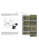
Flushing can be undertaken by utilizing a by-pass or removing the meter from the pipework. If neither is practical
then the meter rotors must be removed prior to flushing
(refer to Maintenance section of this manual for
disassembly).
After flushing or following long periods of shutdown the meter must be purged of air/vapour. This can be achieved
by allowing the liquid to flow through the meter at a slow rate until all air/vapour is displaced. Never run the meter
above its maximum flow or exceed 100kpa (1 bar, 15psi) pressure drop across the meter. Now the meter is ready
for its operation to be confirmed by ensuring correct indication or operation at the receiving instrument(s). Refer if
necessary to fault finding section of this manual.
4.0 Maintenance
Adhering to the installation instructions in this manual should ensure your meter provides the
required operational performance. These are mechanical meters and a periodic maintenance and inspection
regime will maximize the operational availability of the meter.
The frequency of maintenance depends on the application factors including liquid lubricity and abrasiveness and
operational factors such as flowrate and temperature.
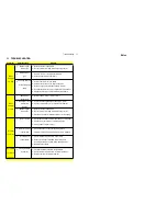
BEFORE
undertaking meter maintenance ensure the following :
Associated alarm(s) or control output(s) are isolated so not to affect the process.
Voltage supply is isolated from the meter.
Liquid supply to the meter is closed off.
The meter is depressurized and liquid drained from the meter.
strainer
flowmeter
isolation valve
isolation valve
by-pass valve
Open downstream valve last
with LCD
register

