background image


16 

2.4.2


Reed Only Pulse Output Board


Applicable Models: 004,006,008 


Applicable Models: 015,025,040, 050, 080, 080E, 100, 100E 


Summary of Contents for Oval Gear

Page 1: ...Industrial Oval Gear Flowmeters with pulse output or electronic display Operation Manual ...

Page 2: ...uct manuals prior to installation and commissioning If further assistance is required please consult the distributor from whom you purchased your flowmeter DISPOSAL WITHIN THE EUROPEAN UNION WEEE Your flow meter and any associated electronics are precision instruments to avoid unnecessary damage please treat them with care CAUTION The WEEE Directive requires that this product be recycled when disp...

Page 3: ...Board 16 2 4 3 Reed Only Outputs as Simple Apparatus 17 2 4 4 Hall Only Output 18 2 4 5 Quadrature Pulse Output 19 2 5 Meter Calibration Factor K Factor Scale Factor 19 2 6 Integral Instruments 19 2 7 Installations in Hazardous Areas 20 2 7 1 ATEX IECEx Flameproof Flowmeters Ex db 20 2 7 2 Conforming Standards 21 2 7 3 Temperature Limits for Flameproof Flowmeters 22 2 7 4 Special Conditions of Use...

Page 4: ...allow the user to set up their meter without the risk of damage allowing the use of the product while the complete instructions are read in detail at a later date Users installing product in Hazardous Areas must read this entire manual before installing their product Damage caused to meters by users who have only read the Quick Start Guide will not be accepted as a justification for a warranty cla...

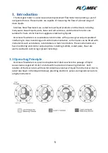
Page 5: ...capable of interfacing to most monitoring and control instrumentation or the meter can be fitted with instruments such as totalisers rate totalisers or batch controllers These instruments also have monitoring and control output options including 4 20mA scaled pulse flow rate alarms and batch control logic preset metering 1 1 Operating Principle Oval Gear flowmeters are positive displacement device...

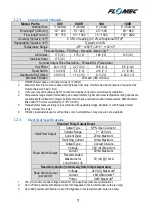
Page 6: ...sh 75 micron 6 1 2 2 Medium Capacity Models Model Prefix 015 025 040 050 Nominal Size 1 2 15mm 1 25mm 1 5 40mm 2 50mm Flow range2 USG min 0 26 10 6 2 6 40 4 66 8 120 Flow range2 L min 1 40 10 150 15 250 30 450 Accuracy liquids 3cP 0 5 of reading 0 2 with optional RT14 3 Repeatability liquids 3cP Typically 0 03 Temperature Range 4oF 250oF 20oC 120oC 4 Pressure Ratings PSI Bar threaded meters only 5...

Page 7: ...for standard pulse output meters higher and lower temperature rating options are available Meters fitted with integral instruments will have a reduced maximum temperature OM008 meters fitted with PPS rotors are limited to 176oF 80oC 5 Flanged meter pressure rating is in accordance with applicable flange standard or with threaded meter rating whichever is lower 6 Filtration requirements are for sof...

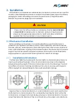
Page 8: ...ation Orientation The flowmeter MUST be mounted with the rotor shafts in a horizontal plane Failure to mount your Oval Gear flowmeter in the correct orientation as shown in the diagrams below will cause the weight of the rotors to bear down on the thrust bearings The short term effects of incorrect mounting orientation will be a loss in accuracy with long term effects ranging from reduced lifespan...

Page 9: ...flowmeter The best piping designs provide a bypass line as shown in the following diagram which allows isolation of the flowmeter and strainer from the main process line The benefits of installing a bypass line are that your system can be purged before start up and any maintenance on the flowmeter or strainer can be carried out quickly and economically without interrupting critical processes 2 1 3...

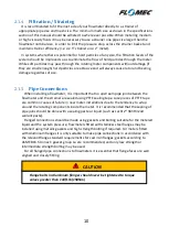
Page 10: ...ortant that no upstream pipe join between the flowmeter and the strainer are sealed using PTFE sealing tape Lose pieces of PTFE tape are common causes of failure in new meter installations due to the tendency to wrap around the rotating components inside the meter It is recommended that the sealing of pipe joins should be done with a sealing paste or liquid such as Loctite 565 thread sealant paste...

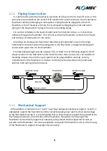
Page 11: ...t 90 degrees in order to limit induced interference Do not combine any inductive loads on the same voltage supply as your flowmeter wiring as these components are commonly sources of high frequency interference that may affect the quality of the output signals Inductive loads on a common voltage source also have the potential for voltage spikes well in excess of the 24V dc limit of the flowmeter e...

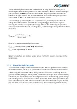
Page 12: ... 𝑢𝑢𝑢𝑢 𝑉𝑉𝑙𝑙𝑙𝑙𝑙𝑙 0 05 102 𝑅𝑅𝑝𝑝𝑝𝑝𝑝𝑝𝑝𝑝 𝑢𝑢𝑢𝑢 Minimum value of pull up resistor 𝑉𝑉𝑝𝑝𝑝𝑝𝑝𝑝𝑝𝑝 𝑢𝑢𝑢𝑢 Voltage that signal is being pulled up to 𝑉𝑉𝑙𝑙𝑙𝑙𝑙𝑙 Low logic voltage threshold Note The hall effect sensor circuitry incorporates 2 x 51 ohm resistors in series with the signal output 2 2 3 Reed Switch Outputs The reed switch output is a two wire normally open SPST voltage free contact ideal for installations...

Page 13: ...ur cover screws with a 4mm Hex Key Allen Key When removing the terminal cover take care not to damage or lose the O Ring Standard Pulse Output Boards utilise a pluggable terminal block which can be removed for fitment of wires Reed Only Pulse Output Boards use Cage Clamp terminal blocks which require insertion of a screw driver into the wedging slot as show below All wiring requires a 0 1 2 5mm wi...

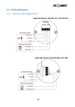
Page 14: ...14 2 4 Wiring Diagrams 2 4 1 Standard Pulse Output Board Applicable Models 006 008 015 025 040 050 Applicable Models 004 080 080E 100 100E ...

Page 15: ...e enabled on the Reed Switch output by wiring the negative terminal of the reed switch terminal 5 to the GND terminal terminal 2 When not using filtering on the Reed Switch output the polarity of the wiring is not important 3 Installing a current limiting resistor is recommended to extend the life of the Reed Switch device 800Ω is recommended as a minimum resistance value for a 24V system Resistor...

Page 16: ...16 2 4 2 Reed Only Pulse Output Board Applicable Models 004 006 008 Applicable Models 015 025 040 050 080 080E 100 100E ...

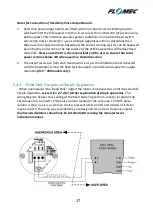
Page 17: ...ed in a Hazardous Area 2 The output resolution from each Reed Switch is as per the calibration sheet delivered with the flowmeter wiring the Reed Switch outputs in parallel will double the output resolution 015 100 models only 2 4 3 Reed Only Outputs as Simple Apparatus When purchased with a Reed Only output the meter can be wired as an Intrinsically Safe Simple Apparatus see section 2 7 4 for fur...

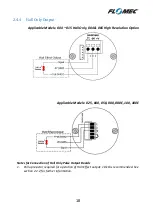
Page 18: ...y 004 006 High Resolution Option Applicable Models 025 040 050 080 080E 100 100E Notes for Connection of Hall Only Pulse Output Boards 1 Pull up resistor required for operation of Hall Effect output 10 kΩ is recommended See section 2 2 2 for further information ...

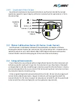
Page 19: ...ents If your flowmeter was purchased with an integral Rate Totaliser then the instrument will be factory wired for reed switch input into the instrument If your flowmeter is fitted with an integral Batch Controller the NPN open collector output from the Hall Sensor is factory wired and programmed If you are unsure of the factory wiring of your instrument remove the instrument bezel to check the wi...

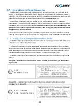
Page 20: ...uctive liquids there may be a risk of electrostatic build up in the liquid It is recommended that the guidance in IEC TS 60079 32 1 is followed 2 7 1 ATEX IECEx Flameproof Flowmeters Ex db ATEX IECEx flameproof Ex db Oval Gear flowmeters are designed and certified for use in either Zone 1 or Zone 2 hazardous areas Flameproof flowmeters must be installed in accordance with hazardous area standards ...

Page 21: ...lation or use review the approval markings on the product and in this manual as well as the conforming standards below to confirm it is appropriate for your country region and site classification ATEX Directive ATEX directive 2014 34 EU EN 60079 0 2012 A11 2013 EN 60079 1 2014 IECEx Scheme IEC 60079 0 2011 Edition 6 0 IEC 60079 1 2014 06 Edition 7 0 ...

Page 22: ...Mb 14oF T 302oF 10oC T 150oC EX d IIB T6 Gb 40oF T 158oF 40oC T 70oC EX d IIB T5 Gb 40oF T 185oF 40oC T 85oC EX d IIB T4 Gb 40oF T 248oF 40oC T 120oC EX d IIB T3 Gb 14oF T 302oF 10oC T 150oC 2 7 4 Special Conditions of Use The following conditions must be adhered to for use service or maintenance of a Flameproof EXd flowmeter o Flamepaths are not intended to be repaired contact manufacturer o The ...

Page 23: ...nt of a 5mm ring terminal Applicable Models 004 006 008 all High Pressure models Applicable Models 015 025 040 050 080 080E 100 100E The use of the internal earth connection as the only earthing connection may be acceptable with wiring systems using steel wire armoured cable or metallic conduit For all other installations an external earthing connection must be used which may be connected to the e...

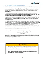
Page 24: ...x schemes meters purchased with the Reed Only option can be used as an Intrinsically Safe simple apparatus if the reed switch output is used in conjunction with suitably certified associated equipment The use of simple apparatus is defined in the international standard EN60079 11 and in many countries regions is allowed to be used in all hazardous areas with a temperature class of T4 provided it i...

Page 25: ...ms that have been shut down for long periods of time Do not start up your system for the first time by opening all valves and turning on the pump To safely start a meter for the first time the best procedure is to eliminate the majority of the air volume in your piping system using the bypass line described earlier After bleeding the majority of the air through the bypass line the remainder of the...

Page 26: ...ep 3 Ensure flow is present No flow or lower than normal minimum flow may be attributed to a blocked strainer jammed or damaged rotors within the flowmeter a malfunctioning pump closed valves or low liquid level in feeder tank Step 4 Ensure oval gears within meter are rotating Rotation of the oval gears can be heard by holding a screw driver blade to the meter body and pressing the handle hard aga...

Page 27: ...t measuring chamber for damage and consult manufacturer for advice Output signal interference Confirm correct wiring with shielded cable Check all electrical connections for firmness and continuity No Output from Flowmeter Rotors jammed If meter has been recently field serviced check that rotors are not installed upside down or incorrectly meshed Check for obstruction due to foreign particles Clea...

Page 28: ...ational conditions of the meter and the criticality of the system it is the user s responsibility to determine inspection frequency however the manufacturer can provide guidance For any installations that require in situ cleaning CIP it is important that the cleaning or flushing procedures do not produce operating conditions that are outside of the acceptable flow rate pressure or temperature rati...

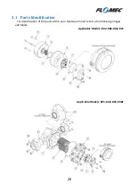
Page 29: ...29 3 1 Parts Identification For identification of the parts within your Oval Gear meter refer to the following images and tables Applicable Models 004 006 008 015 Applicable Models 025 040 050 050E ...

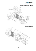
Page 30: ...30 Applicable Models 080 080E 100 100E Applicable Models 025P ...

Page 31: ...e rotors 2 can now be removed and inspected If the meter is fitted with an integral instrument the instrument display assembly must be removed in order to gain access to the instrument terminal connections instrument battery or pulse output board This is achieved by undoing the 4 bezel screws and separating the display assembly from its base Do not stress or damage the wires that connect the displ...

Page 32: ...other Rotate the rotors slowly by hand to ensure they are correctly fitted at the same time check the rotor shafts rotor bearings for wear If you are able to rotate the engaged rotors through a complete 360 then you have installed them at the correct 90 degree angle Fit the O ring into the groove and assemble the meter cap onto the meter body small meters are visibly aligned using a small dimple o...

Page 33: ...pment Directive Compliance is declared according to Article 4 paragraph 3 SEP Annex II table 3 Models OM050H OM100A and OM100E are PED compliant under SEP only for Group II liquids according to Annex II table 4 When purchased as EXd these products are additionally in conformance with 2014 34 EU ATEX Directive EN 60079 0 2004 Electrical apparatus for explosive gas atmosphere Part 0 General requirem...

Page 34: ...34 Notes ...

Page 35: ...35 Notes ...

Page 36: ...ries Inc 5252 East 36th St North Wichita KS USA 67220 3205 888 996 3837 For Technical Assistance warranty replacement or repair outside North or South America contact your Flomec Distributor or contact GPI Australia 1 16 Atkinson Road Taren Point NSW 2229 Sydney Australia 61 02 9540 4433 www flomec net Industrial Oval Gear Meter Instruction Manual 1314009 Rev 1819 ...

Reviews: