background image

-

2

-

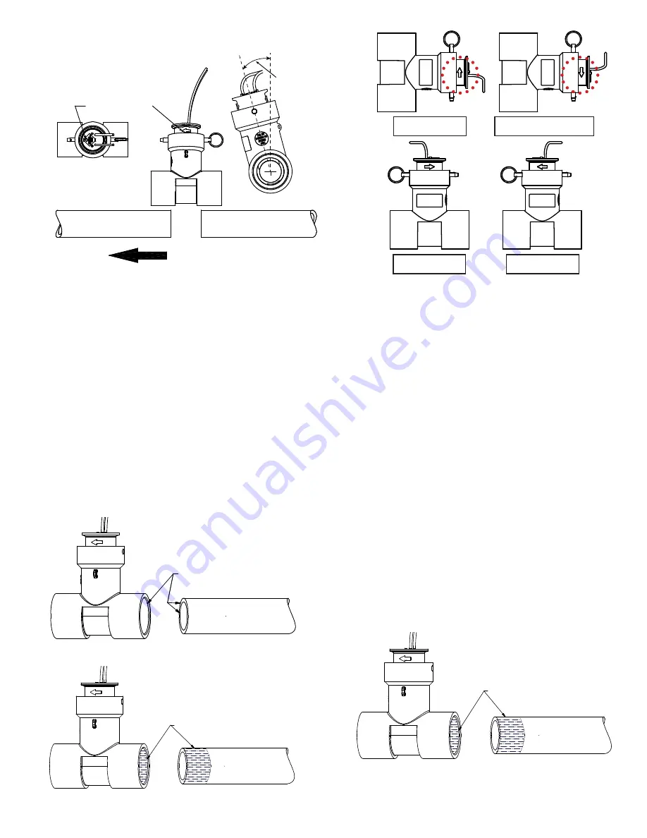
Figure 1a

Figure 1b

Figure 2

Figure 3

Figure 4

  FLOW DIRECTION

10Xs

5Xs

DOWNSTREAM

UPSTREAM

INSTALL AT
ANGLE, IF
POSSIBLE

PAGE 8

INSERT

TOP VIEW

FLOW DIRECTION

ARROW

GENERAL INSTALLATION PROCEDURE (continued)

TEE INSTALLATION (FLOMEC TEE ONLY)

NOTE: 

It is recommended to install Tee at an angle. The water lines are not supposed to have air in them, however, 

sometimes very minute pockets of air can get trapped in the QS200. Installing at an angle helps reduce the consequences  

of this issue. 

IMPORTANT:

 The 1 inch line size FLOMEC

®

 Tee should be installed at a 45 degree angle.

1.  Remove all burrs from inner and outer diameter 

of PVC pipe that will be connected to the FLOMEC 

Tee. Also, remove inner diameter burrs from 

FLOMEC Tee (See Figure 2).


-

NOTE:

 Installation drawings show the QS200 insert 

in the Tee, but it is recommended to install the Tee 

first without the QS200 insert inside. This will keep 

excess PVC cement off of the QS200 insert.

2.  Clean and apply Primer to pipe ends and tee 

sockets (See Figure 3).

3.  Apply PVC cement to pipe ends and Tee sockets 

and quickly assemble the parts while the cement 

is fluid. Follow the cement manufacturer’s 

instructions (See Figure 4).


-

NOTE:

 Only use PVC cement – Do not try other PVC 

alternatives.


-

NOTE:

 Make sure Tee is tilted at required angle for 

QS200 (1 inch pipe installations will need a larger 

45 degree angle tilt).

4.  Hold the cemented parts together for a minimum 

of 30 seconds.

Below ground installations should be installed with a valve 

box with a minimum of 10 inches thick (deep) layer of 

gravel directly underneath the QS200. The gravel shall be 

through the entire length and width of the valve box. Valve 

box extensions may be needed depending on depth.

APPLY PRIMER

APPLY CEMENT

REMOVE BURRS

 CORRECT

 CORRECT

 NOT CORRECT

 CORRECT

Summary of Contents for QS200

Page 1: ...f the meter 5 times the pipe s inner diameter downstream of the meter The pipe needs to be full of irrigation water with no air inside Built up sediment on the QS200 s transducers or large debris can greatly hinder the meter s performance Keep the following in mind when installing Install QS200 at an angle as shown in Figure 1a 1 inch pipe installations will need a larger angle of 45 degrees Flow ...

Page 2: ...sert in the Tee but it is recommended to install the Tee first without the QS200 insert inside This will keep excess PVC cement off of the QS200 insert 2 Clean and apply Primer to pipe ends and tee sockets See Figure 3 3 Apply PVC cement to pipe ends and Tee sockets and quickly assemble the parts while the cement is fluid Follow the cement manufacturer s instructions See Figure 4 NOTE Only use PVC...

Page 3: ...etrofits 1 The Tee insert bore must be clean before installing the insert and the 2 black O rings on the insert should be fully lubricated a The O rings on the outside of the QS200 Retrofit Insert are square profile O rings When installing in another brand of Tee if the insert fits too tight into the Tee replace the square profile O rings with the round profile O rings included with the QS200 Retr...

Page 4: ... or driving wedge between the insert lip and top of the tee to break the insert loose and gain room between the insert lip and tee to use the U formed end to lever the insert up and out 2 An alignment tool to align the pin holes of the new insert with the pin holes in the tee 3 A cleaning tool for clearing debris from the valve box lid groove or other crevices The U formed end is designed for use ...

Page 5: ...all New QS200 Insert FLOMEC Multi Tool PIN HOLE ALIGNMENT For easy pin install CLEAN LID GROOVE Remove dirt roots debris Figure 10 Remove Old Insert From Tee with FLOMEC Multi Tool PRY UP To break a stuck insert loose LEVERAGE To Lift insert up and out DRIVING WEDGE To lift insert more ...

Page 6: ... from the meter to the controller decoder to prevent ground interference Make sure cable length is within controller decoder manufacturer s recommendation 7 Connect the and ends as described in Step 3 of this section of the direct burial cable to the controller s decoder s flow sensor input or port per controller decoder manufacturer s direction Keep in mind that the flow sensor input typical desi...

Page 7: ...to devices as flow sensor instead of flowmeter 1 Make sure line is full of water with no trapped air 2 Flow meter may take a few minutes to start averaging out flow per irrigation controller displays 3 It is recommended to monitor and observe stabilized flow rates before setting control limits Operation QS200 WIRING INSTALLATION continued RED BLACK DBR Y 6 SPLICE KIT FLOW INSERT TO FLOW ON FLOW SM...

Page 8: ...o putting into service Product should never be operated outside its published specifications for temperature or pressure See specifications for your model When applying power adhere to specifications listed in appropriate electronics manual Make sure flow and pressure have been eliminated from process pipe prior to installing or removing product This product is not approved for use with petroleum ...

Reviews: