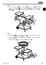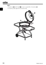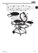
18
FKGW 56 A1
GB
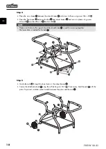
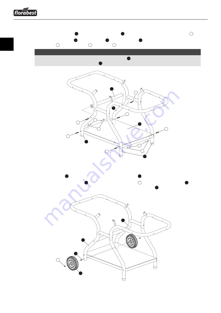
Step 4
♦
Place the cross brace
21
between the wheel braces
19
and screw to these using screw M6 x 45
A
.
♦
Place the fl oor panel
16
between the foot
15
and wheel braces
19
and screw in place using screw
M6 x 45
A
, washer Ø6 x 18
D
and nut M6
H
.
NOTE
►
Please note that only the upper hole of the wheel brace
19
is used for screwing together.
The lower hole is needed for the axle
17
.
Step 5
♦
Guide the axle
17
through the lower holes in the wheel braces
19
.
♦
Secure the attached wheels
18
using the self-locking nuts M10
I
. If necessary, hold the axle
17
with the
pliers. To prevent scratches, place a cloth between the pliers and the axle
17
.
21
19
19
A
A
A
A
A
A
D
H
H
D
15
16
19
18
17
I
19
IB_85798_FKGW56A1_LB1.indb 18
02.01.13 09:58
Summary of Contents for FKGW 56 A1
Page 3: ......


