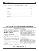

Installation
4
PIPING
Both suction and discharge piping should be indepen-
dently supported at a point near the pump to avoid
strains being placed on the pump. Start all piping at
pump to avoid strains left by a gap.
It is advisable to increase the size of both suction and
discharge piping at the pump if any appreciable run of
pipe is required. Never use a smaller suction pipe than
the suction connection on the pump. Use a pipe wrench
to hold the suction and discharge bosses of the pump
while making up the piping, to avoid putting excess
strain on the pump.
SUCTION PIPE
The suction pipe must be kept free from air leaks. Any
horizontal run of suction piping must have a gradual
upslope towards the pump. Avoid any fittings which
may cause an air trap. A foot valve should be installed
to prevent loss of pump prime.
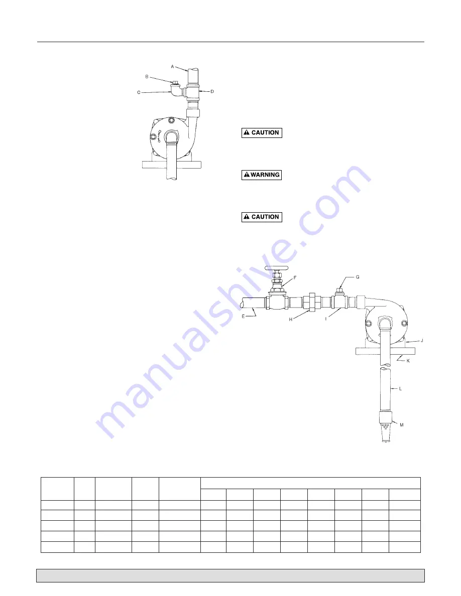
DISCHARGE PIPING
A gate valve and union should be installed in the dis-
charge line. For removal of the pump for service, close
the gate valve, and disconnect the union.
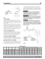
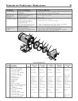
PRIMING THE PUMP
Prime pump by filling both the pump and suction line
completely with water thru the priming tee. Replace
priming plug and start pump. If water is not pumped
immediately it is because all the air has not been evacu-
ated. Stop pump and reprime, following instructions
above. When used with vertical discharge, the vent plug
at the top should be loosened to evacuate air which is
trapped inside the volute. When volute is completely
filled with water, tighten vent plug.
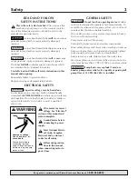
NEVER run pump dry. Running pump
without water may cause pump to overheat, damaging
seal and possibly causing burns to persons handling
pump. Fill pump with water before starting.
NEVER run pump against closed dis-
charge. To do so can boil water inside pump, causing
hazardous pressure in unit, risk of explosion and possi-
bly scalding persons handling pump.
Motor normally operates at high tempera-
ture and will be too hot to touch. It is protected from
heat damage during operation by an automatic internal
cutoff switch. Before handling pump or motor, stop
motor and allow it to cool for 20 minutes.
For parts or assistance, call Flotec Customer Service at
1-800-365-6832
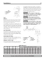
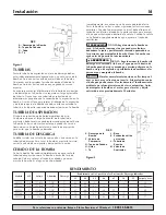
Figure 1
Figure 2
KEY
A - Pump Discharge
B - Priming Plug
C - Street El
D - Tee
KEY
E - Pump Discharge
F - Gate Valve
G - Priming Plug
H - Union
I - Tee
J - Base
K - Solid, level
foundation
L - Suction Piping
M -Foot Valve
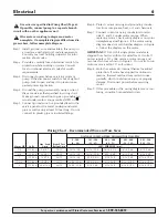
PERFORMANCE
Performance in GPM at Discharge Pressure Shown
Model
HP
Voltage
Inlet
Discharge
25
30
35
40
45
50
55
Max PSI
FP5512
1/2
115/230
1-1/4"
1"
22
13
2
–
–
–
–
36
FP5522
3/4
115/230
1-1/4"
1"
31
25
21
13
–
–
–
43
FP5532
1
115/230
1-1/4"
1"
47
40
35
29
17
–
–
49
FP5542
1-1/2
115/230
1-1/4"
1"
59
52
47
40
30
15
–
51
FP5552
2
230
1-1/2"
1-1/4"
68
62
54
48
38
29
7
57
Summary of Contents for FP5500 Series
Page 20: ...20...