background image

Electrical

6

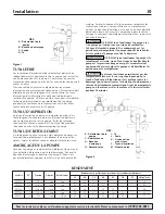
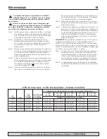
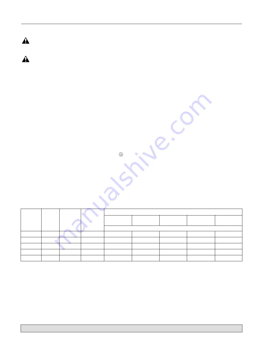
Use wire size specified in Wiring Chart (Page 6).

If possible, connect pump to a separate branch

circuit with no other appliances on it.

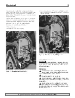
Wire motor according to diagram on motor

nameplate. If nameplate diagram differs from dia-

grams above, follow nameplate diagram.

Step 1. Install, ground, wire and maintain this pump in

accordance with electrical code requirements.
Consult your local building inspector for infor-
mation about codes.

Step 2. Provide a correctly fused disconnect switch for

protection while working on motor. Consult
local or national electrical codes for switch
requirements.

Step 3. Disconnect power before servicing motor or

pump. If the disconnect switch is out of sight of
pump, lock it open and tag it to prevent unex-
pected power application.

Step 4. Ground the pump permanently using a wire of

the same size as that specified in wiring chart.
Make ground connection to green grounding ter-
minal under motor canopy marked GRD. or 

Step 5. Connect ground wire to a grounded lead in the

service panel or to a metal underground water
pipe or well casing at least 10 feet long. Do not
connect to plastic pipe or insulated fittings.

Step 6. Protect current carrying and grounding conduc-

tors from cuts, grease, heat, oil, and chemicals.

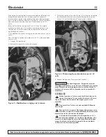
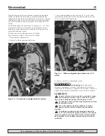
Step 7. Connect current carrying conductors to termi-

nals L1 and L2 under motor canopy. When
replacing motor, check wiring diagram on motor
nameplate against Figure 3. If the motor wiring
diagram does not match either diagram in Figure
3, follow the diagram on the motor.

IMPORTANT:

115/230 Volt single phase models are

shipped from factory with motor wired for 230 volts. If
power supply is 115 volts, remove motor canopy and
reconnect motor as shown in Figure 3. Do not try to run
motor as received on 115 volt current.

Step 8. Motor has automatic internal thermal overload

protection. If motor has stopped for unknown
reasons, thermal overload may restart it unex-
pectedly, which could cause injury or property
damage. Disconnect power before servicing
motor.

Step 9. If this procedure or the wiring diagrams are con-

fusing, consult a licensed electrician.

For parts or assistance, call Flotec Customer Service at 

1-800-365-6832

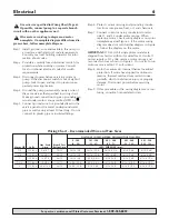
DISTANCE IN FEET(METERS) FROM MOTOR TO SUPPLY

0 - 100 

101 - 200 

201 - 300 

301 - 400 

401 - 500 

Max. Load

Branch Fuse

(0 - 30) 

(31 - 61) 

(62 - 91) 

(92 - 122) 

(123 - 152) 

Motor HP

Volts

Amp

Rating Amp

AWG WIRE SIZE (mm

2

)

1/2

115/230

9.4/4.7

15/15

14/14 (2/2)

10/14 (5.5/2)

10/14 (5.5/2)

6/14 (14/2)

6/12 (14/3)

3/4

115/230

12.2/6.1

20/15

12/14 (3/2)

10/14 (5.5/2)

8/14 (8.4/2)

6/12 (14/3)

6/12 (14/3)

1

115/230

14.8/7.4

20/15

12/14 (3/2)

8/14 (8.4/2)

6/14 (14/2)

6/12 (14/3)

4/10 (21/5.5)

1-1/2

115/230

19.2/9.6

30/15

10/14 (5.5/2)

8/14 (8.4/2)

6/12 (14/3)

4/10 (21/5.5)

4/10 (21/5.5)

2

115/230

24.0/12.0

30/15

10/14 (5.5/2)

6/14 (14/2)

6/12 (14/3)

4/10 (21/5.5)

4/10 (21/5.5)

Wiring Chart – Recommended Wire and Fuse Sizes

Summary of Contents for FP5500 Series

Page 1: ...nt Pi ces Pour plus de renseignements concernant l utilisation l installation ou l entretien Composer le 1 800 365 6832 Fran ais Pages 8 13 Instalaci n Operaci n Piezas Para mayor informaci n sobre el...

Page 2: ...a qualified electrician GENERAL SAFETY Do not touch an operating motor Modern motors are designed to operate at high temperatures To avoid burns when servicing pump allow it to cool for 20 minutes aft...

Page 3: ...red or replaced at FLOTEC s option subject to the terms and conditions set forth below General Terms and Conditions Purchaser must pay all labor and shipping charges necessary to replace product cover...

Page 4: ...prime following instructions above When used with vertical discharge the vent plug at the top should be loosened to evacuate air which is trapped inside the volute When volute is completely filled wit...

Page 5: ...r 1 2 wrench and turn the volt age selector dial counterclockwise until 115 shows in the dial opening 4 Reinstall the motor cover Hazardous voltage Can shock burn or cause death Disconnect power to mo...

Page 6: ...ls L1 and L2 under motor canopy When replacing motor check wiring diagram on motor nameplate against Figure 3 If the motor wiring diagram does not match either diagram in Figure 3 follow the diagram o...

Page 7: ...9 10 10 10 11 13 12 683 0294 FL Key Part FP5512 08 FP5522 08 FP5532 08 FP5542 08 FP5552 08 No Description Qty 1 2 HP 3 4 HP 1 HP 1 1 2 HP 2 HP 1 Motor 115 230V 60 Cycle Single Phase 1 A100CLL A100DLL...

Page 8: ...ratures lev es Pour ne pas se br ler lorsque l on interviendra sur la pompe la laisser refroidir pendant 20 minutes apr s l avoir arr t e avant de la toucher Ne pas laisser geler la pompe ni aucun au...

Page 9: ...ermes et condi tions stipul s ci dessous Conditions g n rales L Acheteur s engage payer tous les frais de main d uvre et d exp dition n cessaires au remplacement du produit couvert par la garantie Cet...

Page 10: ...l le bouchon d a ration qui se trouve en haut doit tre desserr de fa on chasser l air emprisonn dans la volute Lorsque la volute est compl tement remplie d eau resserrer le bouchon d a ration NE JAMAI...

Page 11: ...on vers la gauche jusqu ce que la valeur 115 soit affich e dans l ouverture du cadran 4 Reposer de nouveau le couvercle du moteur Tension dangereuse Risque de secousses lectriques de br lures voire de...

Page 12: ...nsporteurs de courant sur les bornes L1 et L2 qui se trouvent sous le carter du moteur Lorsque l on remplace le moteur comparer le sch ma de c blage de la plaque signal tique par rapport la Figure 3 S...

Page 13: ...rt e et mal ancr e toute contrainte sur la pompe 1 2 3 4 5 6 8 7 9 10 10 10 11 13 12 683 0294 FL N de D signation FP5512 00 FP5522 00 FP5532 00 FP5542 00 FP5552 00 r f des pi ces Qt 1 2 CV 3 4 CV 1 CV...

Page 14: ...ados para operar a temperaturas altas Para evitar quemaduras al realizar el servicio a una bomba d jela enfriar por 20 minutos despu s de apagarla No permita que la bomba o cualquier componente del s...

Page 15: ...consumidor original ste ser reparado o reemplazado a opci n de FLOTEC sujeto a los t rminos y a las condiciones indicadas a continuaci n T rminos y Condiciones Generales El comprador debe pagar todos...

Page 16: ...o las instrucciones anteriores Cuando la descarga sea vertical debe aflojarse el tap n de ventilaci n situado en la parte superior para evacuar el aire que est atrapado dentro de la voluta Cuando la v...

Page 17: ...e tensi n hacia la izquierda hasta que se vea 115 en la abertura del cuadrante 4 Vuelva a instalar la cubierta del motor Tensi n peligrosa Puede causar choques quemaduras o muerte Desconecte la corrie...

Page 18: ...os Paso 7 Conecte los conductores que llevan la corriente a los bornes L1 y L2 bajo el techo del motor Cuando cam bie el motor inspeccione el diagrama de cableado en la placa de f brica del motor cont...

Page 19: ...l anclada aliviar los esfuerzos en el conjunto de la bomba 1 2 3 4 5 6 8 7 9 10 10 10 11 13 12 683 0294 FL No de Descripci n FP5512 00 FP5522 00 FP5532 00 FP5542 00 FP5552 00 Ref de las Piezas Cant 1...

Page 20: ...20...

Reviews: