background image

Installation

5

For parts or assistance, call Flotec Customer Service at 

1-800-365-6832

NOTE:

Installation of a low pressure safety cutoff

switch on the pump discharge is recommended (and
may be required by your local code) to shut off the
power in case of low discharge pressure (caused by
broken pipe, etc.).                                                     

2. Mount the pump on a solid base in the location you

have decided on. 

3. Choose a time that will allow you to shut off the

water to the household while you install the
PressureMate.

4. Shutoff the main water supply valve to the household.
5. Open any faucet to relieve water pressure in the

plumbing. Once the water pressure is relieved, close
the faucet.

6. READ STEP 6 COMPLETELY BEFORE STARTING TO

WORK ON IT. You must remove a length of pipe
from the main water supply line to allow installation
of elbows for the PressureMate. The locations of the
cuts must take into consideration the size of the
elbows being used, the length of the threads in
threaded joints or the overlap in glued or soldered
joints, etc.. Position the elbows in line with the pump
suction and discharge threads. There may be slight
water leakage while cutting the pipe. Remove any
burrs or shavings caused by the cutting tool. 

NOTE: 

Galvanized pipe may not need to be cut. If

there is a union close to the pump location, disas-
semble the union and remove (unscrew) pipe back
past the pump location. Have new lengths of pipe cut
and threaded to allow for the pump installation. 

NOTE:

Both female suction and male discharge ports

have 1” NPT threads. Depending on your type of
connection and the size of your home’s piping, you
may need to install adapters on the ports.

7. Once the short piece of pipe is removed, the piping

above the cut can be drained to prevent water mess.
Place a pail under the opening going to the house-
hold. Open the highest faucet in the system to let in
air so the water can fall out of the pipes into the pail.
Once it’s drained, close the faucet.

8. Install the elbows in the main water supply line. Point

them toward the pump.

Risk of burst hose and flooding.

Do not

install with flexible hoses. Use only rigid piping that
meets code.

9. Install piping from elbows to pump including a union

in each line and a check valve in the pump suction
line. The arrow on the check valve must point to the
pump suction (see Figure 2). If not already in the
plumbing system, install a pressure relief valve in the
pump discharge line capable of passing the full pump
flow at 100 psi (689 kPa). If local code requires
installation of a pressure relief valve capable of han-
dling the full pump flow at a pressure less than 100
psi (689 kPa), follow the code requirements. A low
pressure safety cutoff switch should also be installed
in the discharge line, and may be required by your
local codes.

10. With all pipe and fittings installed and sealed, turn on

the main water supply slowly to pressurize the system
and check for leaks. If any leaks appear, turn the
main valve off, open a faucet to relieve the pressure,
and repair the leak. Repeat this step until there are no
leaks in the system.

11. Open a faucet to release the air from the pipes and

allow water to flow. When a steady stream of water
flows out of the faucet, the pump is full of water and
fully primed. Close the faucet.

12. Turn the controller knob to the desired pressure for

the pump to turn on. The PressureMate comes factory
preset at 30 psi (207 kPa), and we recommend start-
ing there and adjusting it later according to your
experience with the system.

13. Before continuing with the installation, see the sections

of this manual titled “Electrical Connections”,
“Automatic Pressure Controller”, “Normal Operation”,
and “When Does The Pump Stop Operating” for
detailed information on how the system functions.

14. At this point, you can plug in the pump for the first

time. When you plug in the power cord, the pump
will start and run for 15 seconds regardless of the
controller setting. If the inlet pressure is above the set
point, the pump will stop after 15 seconds. 

15. When the pump is running and after it shuts off auto-

matically, the system is at the boosted pressures.
Inspect the pipe and fittings again for water leaks. If
any leaks appear, unplug the pump, turn the water
main valve off, open a faucet to relieve the pressure
and repair the leak. Repeat this step until there are no
leaks in the system.

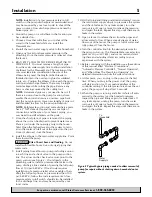
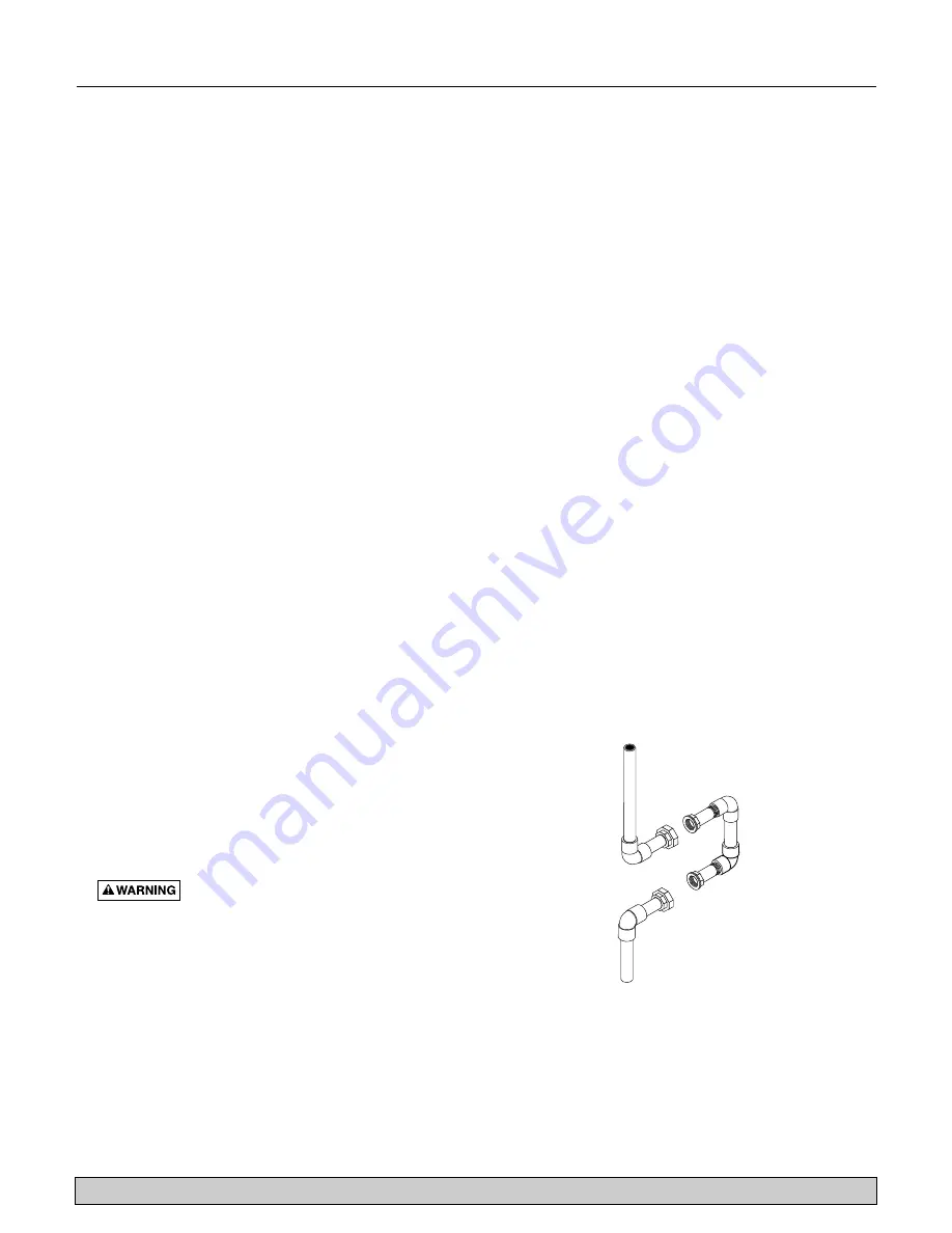
Water
Supply In

To 
Household


Figure 3:Typical bypass piping needed to allow removal of
pump for repair without shutting down household water
system.

Summary of Contents for PressureMate FP4815 Series

Page 1: ... Installation Fonctionnement Pièces Pour plus de renseignements concernant l utilisation l installation ou l entretien Composer le 1 800 365 6832 Français Pages 9 15 Instalación Operación Piezas Para mayor información sobre el funcionamiento instalación o mantenimiento de la bomba Llame al 1 800 365 6832 Español Paginas 16 22 2003 PRINTED IN U S A FP591 Rev 3 20 03 Series FP4815 P O Box 342 Delava...

Page 2: ... parts overheat pump which can cause burns to people handling or servicing pump and will void warranty 6 Risk of fire or explosion To avoid risk of fire and explosion Pump Water Only with this pump Do not pump flammable liquids or chemicals Do not use the pump near gas pilot lights or where chemical or gas fumes are present Use of an electric pump with liquids other than water or in an atmos phere...

Page 3: ...he sole judgement of FLOTEC have been sub ject to negligence abuse accident misapplication tampering alteration nor due to improper installation operation maintenance or storage nor to other than normal application use or service including but not limited to opera tional failures caused by corrosion rust or other foreign materials in the system or operation at pressures in excess of recommended ma...

Page 4: ...smallest possible number of fittings Long pipe runs and numerous fittings increase friction and reduce the flow of water Support the weight of the piping and pump Do not allow the pump pressure controller or any system components to freeze Freezing will damage the pump and void the warranty Periodically inspect the pump pressure controller and system components NOTE Local code may require a pressu...

Page 5: ...ing from elbows to pump including a union in each line and a check valve in the pump suction line The arrow on the check valve must point to the pump suction see Figure 2 If not already in the plumbing system install a pressure relief valve in the pump discharge line capable of passing the full pump flow at 100 psi 689 kPa If local code requires installation of a pressure relief valve capable of h...

Page 6: ...EMATE Burn Hazard NEVER run the pump dry Running the pump without water may cause pump to overheat and cause burns to persons handling the pump It may also damage the impeller and may damage the seal causing leaking or flooding and will void the war ranty Fill the pump with water before starting it Make sure that the PressureMate has been properly installed primed see page 4 and that the suction p...

Page 7: ...ion if the water supply to the pump fails To protect the pump from running dry 15 seconds after it detects no water the pump will stop operating The PUMP ON LED will go out and The WATER FAILURE LED will begin flashing Restart Make sure that the suction line is not obstruct ed and that it is connected to a water source Press and release the RESET button The PUMP ON LED should light up and The WATE...

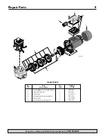
Page 8: ... 6832 1 2 6 4 5 3 4220 0702 Key Part No FP4815 No Description Used 1 2 HP 1 Pump Body Kit includes Bolts 1 FPP1801 2 Internal Parts Kit 1 FPP1870 3 Capacitor 1 171P5750 4 Wiring Box Cover Gasket Kit 1 FPP1802 5 Fan Guard 1 721S1090 6 Shaft Seal and O Ring Kit 1 FPP1850 Model FP4815 ...

Page 9: ...himiques Ne pas utilis er cette pompe près de veilleuses fonctionnant au gaz ni en présence de vapeurs de produits chimiques d essence ou de tout autre produit inflammable L utilisation d une électropompe pour pomper des liquides autres que de l eau ou dans une atmosphère contenant des vapeurs de produits chimiques d essence ou de tout autre produit inflammable risque d enflammer ces liquides ou c...

Page 10: ...ns stipulés ci dessous Conditions générales L Acheteur s engage à payer tous les frais de main d œuvre et d expédition né cessaires au remplacement du produit couvert par la garantie Cette garantie ne couvrira pas les cas de force majeure et ne s appliquera pas aux produits qui du seul avis de FLOTEC ont fait l objet de négligence d utilisation abusi ve ou incorrecte d accident de modification ou ...

Page 11: ...onda tion excessives Utiliser la plus courte longueur de tuyau possible et le moins possible de raccords De grandes longueurs de tuyau et de nombreux raccords augmentent le frottement ce qui diminue le débit de la pompe Supporter le poids de la tuyauterie et de la pompe Ne pas permettre à la pompe à son servorégulateur ni aux composants de système de geler Le gel endommagera la pompe et la garanti...

Page 12: ...et un clapet de non retour sur la conduite d aspiration de la pompe La flèche frappée sur le clapet de non retour doit être orientée vers l aspiration de la pompe se reporter à la Figure 2 Sur la conduite de refoulement poser une soupape de sûreté qui permettra d évacuer tout le débit de la pompe à une pression de 689 kPa 100 lb po2 Si cette stipulation est contraire aux codes respecter les codes ...

Page 13: ... à sec sinon elle risque de surchauffer et les personnes qui la manipuleront risqueront de se brûler L impulseur et le joint de l arbre de la pompe peuvent également être endommagés si la pompe fonctionne à sec ce qui pourrait causer des fuites ou une inondation De plus la garantie sera annulée Avant de démarrer la pompe la remplir d eau S assurer que la pompe PressureMate a été adéquatement insta...

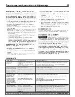
Page 14: ...nctionne si l eau cesse de parvenir à la pompe Pour protéger la pompe contre un fonctionnement à sec 15 secondes après que le servorégulateur aura détecté qu il n y a pas d eau la pompe cessera de fonctionner Le témoin électroluminescent PUMP ON Pompe en marche s éteindra et Le témoin électroluminescent WATER FAILURE Manque d eau clignotera Redémarrage S assurer que la conduite d aspiration n est ...

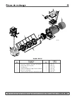
Page 15: ...6 4 5 3 4220 0702 Désignation FP4815 Réf des pièces Qté 1 2 ch 1 Corps de la pompe comprend les boulons 1 FPP1801 2 Trousse des pièces internes 1 FPP1870 3 Condensateur 1 171P5750 4 Trousse de boîte de câblage Couvercle Joints 1 FPP1802 5 Carter du ventilateur 1 721S1090 6 Trousse de joints d arbre et de joints toriques 1 FPP1850 Modèle FP4815 ...

Page 16: ... mente con esta bomba No bombee líquidos ni sustancias químicas inflamables No use la bomba cerca de luces piloto de gas o en áreas en presencia de vapores químicos o de gases El uso de una bomba eléctrica con líquidos que no sean agua o en una atmósfera que contenga vapores químicos o gases podrá inflamar esos líquidos o gases provocando lesiones o muerte debido a una explosión y o un incendio 7 ...

Page 17: ...lazado a opción de FLOTEC sujeto a los términos y a las condiciones indicadas a continuación Términos y Condiciones Generales El comprador debe pagar todos los gastos de mano de obra y transporte nece sarios para reemplazar el producto cubierto por esta garantía Esta garantía no se aplicará a hechos de fuerza mayor ni se aplicará a los productos que a jui cio exclusivo de FLOTEC hayan sido objeto ...

Page 18: ...ería y la menor cantidad posible de accesorios Trayectos de tubería largos y numerosos accesorios aumentan la fricción y reducen el flujo del agua Apoye el peso de la tubería y de la bomba No permita que la bomba el controlador de presión ni ningún componente del sistema se congelen El conge lamiento dañará la bomba y anulará la garantía Inspeccione periódicamente la bomba el controlador de pre si...

Page 19: ...mangueras flexibles Use solamente tubos rígidos que cumplan con las disposi ciones del código 9 Instale la tubería desde los codos a la bomba incluyendo una unión en cada línea y una válvula checadora en la línea de aspiración de la bomba La flecha en la válvula checadora debe apuntar hacia la aspiración de la bomba consulte la Figura 2 Instale una válvula de desahogo de presión en la línea de des...

Page 20: ... NUNCA deje mar char la bomba en seco Si se deja que la bomba marche sin agua ésta se podrá recalentar y podrá quemar a las personas que estén manipulando la bomba También podrá dañar el impulsor y el sello provocando fugas o inundación y anulará la garantía Llene la bomba con agua antes de encenderla Verifique que la PressureMate se haya instalado y cebado debidamente Consulte la Página 4 y que l...

Page 21: ...cionamiento si falla el suministro de agua hacia la bomba Para proteger a la bomba y evitar que marche en seco 15 segundos después de haber detectado el estado de falta de agua la bomba dejará de funcionar Se apagará la luz de BOMBA ENCENDIDA y La luz de FALLA DE AGUA comenzará a centellear Reinicio Asegúrese de que la línea de aspiración no esté obstruida y que esté conectada a una fuente de sumi...

Page 22: ...0 0702 Clave Descripción FP4815 No de la pieza Cantidad 1 2 HP 1 Juego de unidad de bomba incluye pernos 1 FPP1801 2 Juego de repuestos internos 1 FPP1870 3 Capacitor 1 171P5750 4 Juego de caja de cables Cubierta Empaquetadura 1 FPP1802 5 Rejilla de protección 1 721S1090 6 Juego de sello del eje y aro tórico 1 FPP1850 Modelo FP4815 ...

Reviews: