212516 D/GB
14
GB
4.0 Transport
ATTENTION! Always check delivery for completeness and damage!
The carrier (forwarder or railway) has to be informed immediately in case of transport damages.
(see yellow leaflet) The machine is suitable for the transport by forklift or pallet truck.
The general and local regulations for the transport of machinery do apply.
5.0 Setting up the machine
The drilling machine should be set up on a solid base and aligned using a spirit level. If the machine is to be
bolted to the base, ensure that the base plate does not warp in the process. The use of vibration damping
elements is recommended.
6.0 Installation
The machine has been installed ready for use. The power connection follows the circuit layout. Please check
whether kind of current, current voltage and fusing corresponds to the prescribed values.
There must be a protective conductor connection. The main fuse is 16 A. Due to type of construction of this
machine, the leakage current is greater than 3.5 mA. The substitute leakage current TEA should be <15 mA.
The differential current should be < 7.5 mA.
We ask for your kind attention regarding this matter when performing machine tests in context with machine
safety.
7.0 Commissioning
The parts with rust-inhibiting coating should be cleaned carefully. The column should then be lubricated.
The table should be moved up and down several times.
First unlock the emergency push button (optional). The electrical drill guard must be closed (safe position).
Attention! Isolate from mains before removing cover and WAIT 15 MINUTES to allow the DC bus capacitors
to discharge.
8.0 Speed (rpm) display
Every machine displays the speed(rpm) digitally. The actual speed (rpm) is shown within an accuracy of 10 rpm.
9.0 Drill depth display
Every machine displays the nominal/actual drill depth digitally.
The drill depth can also be estimated by using the scale of the stop ring.
10.0 Adjusting the drill depth
Feed the drill bit on top of the surface of the work piece and hold the lever in this position. Push Zero adjustment
but ton. Now when drilling the drill depth can be read out digitally. The stop ring limits the feed in. The stop ring is
used for approximate settings. Therefore pull it right, select the nominal depth, push it back left and drill
"backwards" to "0".
11.0 Spindle feed
The spindle feed is manual by using the lever.
12.0 Adjustment of table
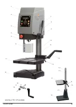
12.1. Machines with a gear rack: Please loosen table locking lever and adjust the height
by using the hand crank.
12.2. Machines without a gear rack: To raise the machine head, please loosen the
locking lever, grab the machine head at the front end and pull it up vertically till
reaching the desired position. Refasten the locking lever! To lower the machine head,
please loosen the locking lever first and push the machine head down by pushing above
the machine’s column into the desired position.
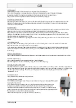
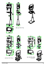
Fasten the locking lever! (see fig. TB 10 Plus, Turbo Drill)


