Manual Glider DCT125 Crosstrainer - 41
4. Use
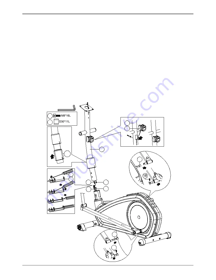
Step 2
1.
Place the resistance knob (97) onto the handlebar post (10) and feed the
adjustment cable (97) downwards. Fasten the Screw with a washer a-1.
2.
Slide the oval cover (49) over the handlebar post (10). As displayed in fig. b.
3.
Connect the upper adjustment cable (97) with the lower adjustment cable (98)
as displayed in figure c-1. Pull the red plastic rotatable tube of the upper cable
back and downwards. The end of the red tube should be placed as displayed
within figure c-4. By rotating the read tube the minimum resistance can increased
or decreased. Rotate clockwise to decrease the resistance and rotate counter
clockwise to increase the resistance.
4.
Check if the cables are connected correctly by rotating the resistance knob. The
end of the upper cable (97) should increase or decrease tension in the lower
cable (98). Connect the upper (29) and lower (30) computer cable.
5.
Assemble the left pedal and right pedal, first place cover (17) on the pedal axle
and then fasten Allen bolt (18) as displayed in fig d-1 and d-2
49
(b)
10
c-1
c-2
c-3
c-4
(a)
d-1
d-2
a-1
a-2
30
29
98
97
17
17
18
97
98
18
17
B
(x2)
(x2)
97
10
a
c-1


