


www.flowair.com |16
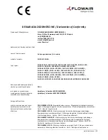
5.4. DOOR CONTACT INSTALLATION
Sample of door contact installation
DCm
– In case of installation in way which is show on drawing
below, connectors 21 and 22 need to be used
Hinged doors
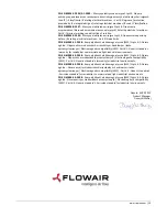
Dce
– In case of installation in way which is show on drawing
below, cable yellow and green need to be used. Other cables
must be isolated.
Hinged door Sliding doors
6. GUIDELINES FOR CONNECTION WITH POWER
SUPPLY
Before connecting the power supply check the correctness of
connection of the fan motor and the controllers. These
connections should be executed in accordance with their
technical documentation.
Before connecting the power supply check whether the
mains voltage is in accordance with the voltage on the device
data shield.
The electrical system supplying the fan motor should be
additionally protected with a circuit breaker against the effects
of a possible short-circuit in the system
Starting the device without connecting the ground conductor
is forbidden.
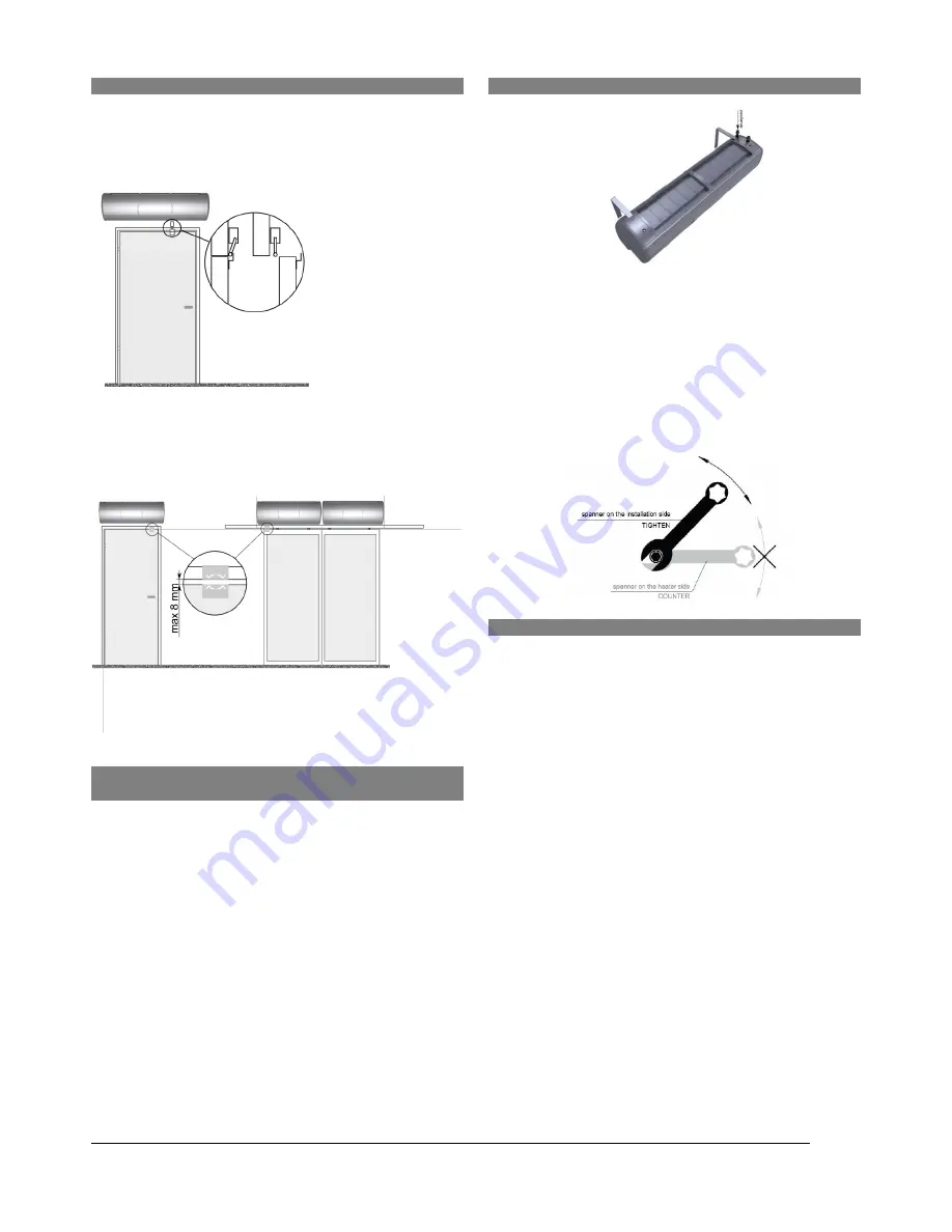
7. GUIDELINES FOR CONNECTION WITH PIPELINE
The connection should be executed in a way which does
not induce stresses.
It is recommended to install vent valves at the highest point
of the system.
The system should be executed so that, in the case of a
failure, it is possible to disassemble the device. For this
purpose it is best to use shut-off valves just by the device.
The system with the heating medium must be protected
against an increase of the heating medium pressure above
the permissible value (1.6 MPa).
While screwing exchanger to pipeline - connecting stubs
has to be hold by wrench.
8. OPERATION
The device is designed for operation inside buildings, at
temperatures above 0
o
C. In low temperatures (below 0ºC)
there is a danger of freezing of the medium.
The manufacturer bears no responsibility for damage of
the heat exchanger resulting from freezing of the medium
in the exchanger.
It is forbidden to place any objects on the
heater or to hang any objects on the connecting stubs.
The device must be inspected periodically. In the case of
incorrect operation of the device it should be switched off
immediately.
It is forbidden to use a damaged device. The manufacturer
bears no responsibility for damage resulting from the use
of a damaged device.
If it is necessary to clean the exchanger, be careful not to
damage the aluminium lamellas.
For the time of performing inspection or cleaning the
device,
the
electrical
power
supply
should
be
disconnected.
In case water is drained from the device for a longer period
of time, the exchanger tubes should be emptied with
compressed air.


