3.8.5 Setting the Flow Output Variables
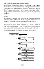
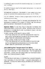
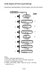
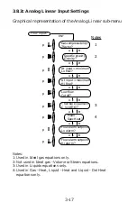
The Flow Output variables determine how the output sig-
nals reflect the compensated flow. The Flow Output sub-
menu is the same no matter which computation or hard-
ware selection you have previously selected.
Notes:
It is not necessary to setup the Flow Output if it is not
required. If setup, the analog out terminal must be con-
nected to a loop to avoid alarm relay from activating.
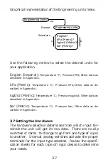
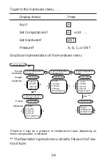
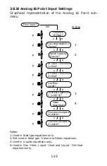
Graphical representation of the Flow Output sub-menu
3-21
Min flow (4mA):
The compensated flow rate value to be repre-
sented by the 4 mA end of the 4 to 20 mA output.
Max flow (20mA :
The compensated flow rate value to be repre-
sented by the 20 mA end of the 4 to 20 mA output.
4-20 mA Example: 4 mA = 10; 20 mA = 1000;
The Flow Computer will sink 4 mA from a flow rate of 0 to 10. Then
it will linearly ramp up to 20 mA; as the flow increases to 1000 (The
current will clamp at 20mA even though the flow may exceed 1000,
until the flow drops back into the active range.)
Digital pulse out Scaling:
Multiplying factor for digital output.
Based on the flow totalizer, this factor multiplies the incremental
counts of the totalized flow and gives a pulse out as required. For
example: A factor of 0.1 puts one pulse out for every 10 increments of
the flow totalizer (0.1 x 10 = 1).
Flow Output?
p
A
B
p
ENT
p
Flow at 4mA out
Min flow?
A
B
Flow at 20mA out
Max flow?
Digital pulse out
Scaling?

