background image


M SLURRY USER


INSTRUCTION ENGLISH  71569241 - 02/08 


Page 4 of 60 


® 

1  INTRODUCTION AND SAFETY 


1.1  General 


These instructions must always be kept close 

to the product's operating location or directly with 
the product.


Flowserve's products are designed, developed and 

manufactured with state-of-the-art technologies in 

modern facilities.  The unit is produced with great care 

and commitment to continuous quality control, utilising 

sophisticated quality techniques, and safety 

requirements. 


We are committed to continuous quality improvement 

and being at your service for any further information 

about the product in its installation and operation or 

about its support products, repair and diagnostic 

services. 


These instructions are intended to facilitate 

familiarization with the product and its permitted use.  

Operating the product in compliance with these 

instructions is important to help ensure reliability in 

service and avoid risks.  The instructions may not take 

into account local regulations; ensure such regulations 

are observed by all, including those installing the 

product.  Always coordinate repair activity with 

operations personnel, and follow all plant safety 

requirements and applicable safety and health laws and 

regulations. 


These instructions must be read prior to 

installing, operating, using and maintaining the 
equipment in any region worldwide.  The 
equipment must not be put into service until all the 
conditions relating to safety noted in the 
instructions, have been met. 


1.2  CE marking and approvals 

It is a legal requirement that machinery and equipment 

put into service within certain regions of the world shall 

conform with the applicable CE Marking Directives 

covering Machinery and, where applicable, Low 

Voltage Equipment, Electromagnetic Compatibility 

(EMC), Pressure Equipment Directive (PED) and 

Equipment for Potentially Explosive Atmospheres 

(ATEX). 


Where applicable, the Directives and any additional 

Approvals, cover important safety aspects relating to 

machinery and equipment and the satisfactory 

provision of technical documents and safety 

instructions.  Where applicable this document 

incorporates information relevant to these Directives.  

To establish approvals and if the product itself is CE 

marked, check the serial number plate and the 

Certification.  (See section 9, 

Certification

.)


1.3  Disclaimer 

 
Information in these User Instructions is believed 
to be reliable. In spite of all the efforts of Flowserve 
Corporation to provide sound and all necessary 
information the content of this manual may appear 
insufficient and is not guaranteed by Flowserve as 
to its completeness or accuracy

.


Flowserve manufactures products to exacting 

International Quality Management System Standards 

as certified and audited by external Quality Assurance 

organisations.  Genuine parts and accessories have 

been designed, tested and incorporated into the 

products to help ensure their continued product quality 

and performance in use.  As Flowserve cannot test 

parts and accessories sourced from other vendors the 

incorrect incorporation of such parts and accessories 

may adversely affect the performance and safety 

features of the products.  The failure to properly select, 

install or use authorised Flowserve parts and 

accessories is considered to be misuse.  Damage or 

failure caused by misuse is not covered by Flowserve's 

warranty.  In addition, any modification of Flowserve 

products or removal of original components may impair 

the safety of these products in their use. 


1.4  Copyright 

All rights reserved.  No part of these instructions may 

be reproduced, stored in a retrieval system or 

transmitted in any form or by any means without prior 

permission of Flowserve Pump Division. 


1.5  Duty conditions 

This product has been selected to meet the 

specifications of your purchaser order.  The 

acknowledgement of these conditions has been sent 

separately to the Purchaser.  A copy should be kept 

with these instructions. 


The product must not be operated beyond the 

parameters specified for the application.  If there is 
any doubt as to the suitability of the product for the 
application intended, contact Flowserve for advice, 
quoting the serial number.


If the conditions of service on your purchase order are 

going to be changed (for example liquid pumped, 

temperature or duty) it is requested that you/the user 

seek our written agreement before start up.


Summary of Contents for 10M234

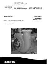
Page 1: ...and Severe Duty includes MX MS options PCN 71569241 02 08 E Installation Operation Maintenance Компания ПромХимТех официальный дистрибьютор насосов Flowserve www promhimtech ru Тел 8 800 250 01 54 e mail zakaz promhimtech ru ...

Page 2: ...brication Methods 27 5 2 Pump lubricants 28 5 3 Direction of rotation 29 5 4 Guarding 29 5 5 Priming and auxiliary supplies 29 5 6 Starting the pump 30 5 7 Running the pump 30 5 8 Stopping and shutdown 31 5 9 Hydraulic mechanical and electrical duty 31 6 MAINTENANCE 32 6 1 General 32 6 2 Maintenance schedule 32 6 3 Spare parts 35 6 4 Recommended spares and consumable items35 6 5 Tools required 35 ...

Page 3: ...ral assembly drawings see 8 48 Grouting 4 4 21 Guarding 5 4 29 Handling 2 2 9 Hydraulic mechanical and electrical duty 5 9 31 Lifting 2 3 11 Location 4 1 21 Lubrication schedule see 5 2 Pump lubricants 28 Maintenance schedule 6 2 32 Piping 4 7 24 Priming and auxiliary supplies 5 5 29 Reassembly see 6 10 Assembly 36 Replacement parts see 6 3 and 6 4 34 Safety electrical see 4 9 26 Safety protection...

Page 4: ...ons Where applicable this document incorporates information relevant to these Directives To establish approvals and if the product itself is CE marked check the serial number plate and the Certification See section 9 Certification 1 3 Disclaimer Information in these User Instructions is believed to be reliable In spite of all the efforts of Flowserve Corporation to provide sound and all necessary ...

Page 5: ...ucts used in potentially explosive atmospheres section 1 6 4 also applies PREVENT EXCESSIVE EXTERNAL PIPE LOAD Do not use pump as a support for piping Do not mount expansion joints unless allowed by Flowserve in writing so that their force due to internal pressure acts on the pump flange ENSURE CORRECT LUBRICATION See section 5 Commissioning startup operation and shutdown START THE PUMP WITH OUTLE...

Page 6: ...ild up of explosive mixtures Prevent the generation of sparks Prevent leakages Maintain the pump to avoid hazard The following instructions for pumps and pump units when installed in potentially explosive atmospheres must be followed to help ensure explosion protection Both electrical and non electrical equipment must meet the requirements of European Directive 94 9 EC 1 6 4 1 Scope of compliance ...

Page 7: ...being run against a closed valve generating high liquid and casing external surface temperatures it is recommended that users fit an external surface temperature protection device Avoid mechanical hydraulic or electrical overload by using motor overload trips temperature monitor or a power monitor and make routine vibration monitoring checks In dirty or dusty environments regular checks must be ma...

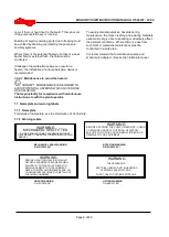
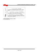
Page 8: ...the ambient conditions Where there is a risk from such tools or materials maintenance must be conducted in a safe area It is recommended that a maintenance plan and schedule is adopted See section 6 Maintenance 1 7 Nameplate and warning labels 1 7 1 Nameplate For details of nameplate see the Declaration of Conformity 1 7 2 Warning labels WARNING MECHANICAL SEAL FITTED DO NOT ADJUST PUMP CLEARANCE ...

Page 9: ...M SLURRY USER INSTRUCTION ENGLISH 71569241 02 08 Page 9 of 60 LUBRICATION WARNING QF 440 R01 2124841 Oil lubricated units only ...

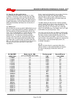
Page 10: ... characteristics of the building The levels specified in the table below are estimated and not guaranteed The dBA values are based on the noisiest ungeared electric motors that are likely to be encountered They are Sound Pressure levels at 1 m 3 3 ft from the directly driven pump for free field over a reflecting plane For estimating LwA sound power level re 1 pW add 14dBA to the sound pressure val...

Page 11: ...ry during assembly Turn the rotor over by hand at least once a week to maintain a protective film on the bearing components 2 4 2 LONG TERM STORAGE More than precautions are required if long term storage in excess of 90 days from factory shipment is unavoidable The internal surfaces of the pump should be sprayed with a rust preventative such as a water soluble oil or other suitable alternative Par...

Page 12: ...ces are coated with a rust preventative compound and openings are provided with covers or plugs Shaft packing when required is shipped with the pump and should not be installed until the pump is ready to run Mechanical seals when provided are factory installed and adjusted prior to shipment The axial impeller running clearance is preset at the factory but should be checked prior to final alignment...

Page 13: ...customer 3 4 Performance and operating limits This product has been selected to meet the specifications of your purchase order see section 1 5 The following data is included as additional information to help with your installation It is typical and factors such as temperature materials and seal type may influence this data If required a definitive statement for your particular application can be o...

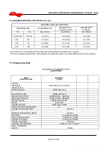
Page 14: ...ction and compatibility with the slurry product 3 4 3 MAXIMUM WORKING PRESSURES bar psi 3 5 Engineering Data MATERIALS OF CONSTRUCTION LIQUID END BASIC CONSTRUCTION MATERIAL CLASS CASING IMPELLER WEAR PLATE ASTM A532 CL III TYPE A STUFF BOX HD ASTM A48 CL35 SUCTION COVER ASTM A48 CL35 PROTECTOR PLATE HARD STEEL 360 BHN IMPELLER SPACER HARD STEEL 360 BHN SHAFT SLEEVE ASTM A743 CG3M SHAFT AISI 1045 ...

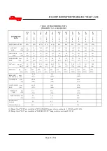
Page 15: ...23 0 9 28 1 1 18 0 7 53 2 1 71 2 8 WK2 wet kg x m2 lb ft2 12 2 8 0 11 2 6 0 21 4 9 0 44 11 0 82 19 2 9 36 2 9 37 2 96 70 5 75 136 1 81 43 3 62 86 PUMP WT Kg Lbs 241 530 264 580 286 630 391 860 486 1070 714 1570 1045 2300 1114 2450 5830 2650 832 1830 1009 2220 IMPELLER mm CLEARANCE IN 0 38 015 0 76 030 1 14 045 O D SLEEVE mm IN 50 80 2 00 76 20 3 00 95 25 3 75 I D STUFFING mm BOX IN 69 85 2 75 101 ...

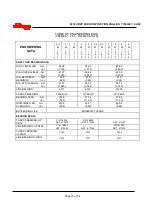
Page 16: ...82 55 3 250 DIA BETWEEN mm BEARINGS in 63 5 2 50 91 9 3 62 91 9 3 62 DIA AT COUPLING mm in 41 27 1 625 63 50 2 500 85 72 3 375 LINE BEARING 6311 6316 21320 THRUST BEARING 7309 BUA 7314 BUA 7318 BUA BEARING SPAN mm in 193 8 7 63 279 4 11 00 279 4 11 00 NOM IMPELLER mm OVERHANG in 207 8 8 18 204 7 8 06 245 4 9 66 B10 BEARING LIFE MINIMUM 3 YEARS BEARING SEALS THRUST BEARING LIP SEAL C R 16246 NAT 47...

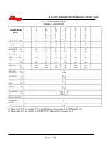
Page 17: ...7 64 2 5 91 3 6 81 3 2 81 3 2 WK2 wet kg x m2 lb ft2 14 2 336 22 7 537 33 1 784 8 83 209 12 6 298 12 6 298 PUMP WT Kg Lbs 1982 4360 2300 5060 2590 5700 1582 3480 2100 4620 2159 4750 IMPELLER mm CLEARANCE in 1 5 0 06 O D SLEEVE mm IN 120 7 4 75 I D STUFFING mm BOX IN 152 4 6 00 DEPTH mm IN 116 3 4 58 PACKING SIZE mm in 15 9 x 15 9 5 8 x 5 8 RINGS OF PACKING 5 Recommended PACKING L5 Alternative Pack...

Page 18: ... IMPELLER mm in 98 6 3 88 DIA UNDER SLEEVE mm in 108 0 4 250 DIA BETWEEN mm BEARINGS in 146 1 5 75 DIA AT COUPLING mm in 104 78 4 125 LINE BEARING 22226C THRUST BEARING QJ322 NU322 BEARING SPAN mm in 513 20 20 NOM IMPELLER mm OVERHANG in 355 13 96 B10 BEARING LIFE MINIMUM 3 YEARS BEARING SEALS THRUST BEARING LIP SEAL NAT 417511 LINE BEARING LIP SEAL C R 42419 NAT 416556 THRUST BEARING O RING 276 L...

Page 19: ... 4 1510 234 MAX SPHERE DIA mm in 55 9 2 2 68 6 2 7 48 3 1 9 96 5 3 8 40 6 1 6 40 6 1 6 50 8 2 0 61 2 4 61 2 4 WK2 kg x m2 lb x ft2 1 01 23 9 1 32 31 3 83 19 8 93 22 0 1 57 37 2 1 39 33 0 1 64 38 8 1 88 44 5 3 91 92 9 PUMP WT kg lb 820 1808 992 2188 644 1420 816 1800 903 1990 1021 2250 848 1870 984 2170 1429 3150 IMPELLER AXIAL mm CLEARANCE in 1 5 0 060 1 7 0 065 1 8 0 070 STUFFING BOX DATA O D SLE...

Page 20: ...LEEVE mm in 108 0 4 25 138 7 5 46 160 0 6 30 DIA BETWEEN mm BEARINGS in 114 3 4 50 DIA AT COUPLING mm in 73 03 2 875 LINE BEARING 23228 24034HL AXIAL THRUST BEARING RADIAL 29326E 22226C 29334E 23134HL BEARING SPAN mm in 293 4 11 55 NOM IMPELLER mm OVERHANG in 312 2 12 29 B10 BEARING LIFE MINIMUM 3 YEARS BEARING SEALS THRUST BEARING LIP SEAL C R 47394 GARL 53x2837 C R 57510 GARL 53x3275 LINE BEARIN...

Page 21: ... to allow for wedges or shims or levelling nuts under the baseplate and a washer heavy hex nut and hex jam nut for retention Since baseplate levelling is performed after the foundation has cured it is best to use extra long bolts that can be shortened after the installation is complete 4 4 Baseplate installation Position the baseplate and pump next to the foundation and clean the foundation surfac...

Page 22: ...coupling hub faces are not always mounted flush with the ends of the shafts Place the driver on the baseplate such that the correct spacing is obtained between the two half couplings In the case of electric motors such as those with sleeve bearings it may be necessary to run the motor to establish the rotor magnetic center Consult the manufacturer s instruction manual for details The purpose of th...

Page 23: ...he pump and driver shafts and each coupling hub diameter and face should be checked Occasionally due to practical and unavoidable manufacturing tolerance build up associate with the pump coupling and driver it may be necessary to match up the two coupling hubs in the most advantageous relative angular position in order to achieve an acceptable alignment Do not install the coupling spacer or sleeve...

Page 24: ...he grout has set sufficiently remove the wooden forms and finish off the sides and top as desired At the same time roughen the grout surface inside the baseplate Cover with wet burlap and allow the grout to cure for at least 40 hours After grouting has cured shims and levelling nuts should be removed or backed off Tighten down baseplate to the new grout to put bolts in tension and ensure rigidity ...

Page 25: ...4500 2980 2200 4610 3400 6670 1500 5340 1200 8000 1800 350 14 6370 4700 3120 2300 4750 3500 8900 2000 7120 1600 5780 1300 6370 4700 3120 2300 4750 3500 7120 1600 5780 1300 8900 2000 400 16 7320 5400 3660 2700 5420 4000 10230 2300 8450 1900 6670 1500 7320 5400 3660 2700 5420 4000 8450 1900 6670 1500 10230 2300 450 18 8200 6050 4200 3100 6100 4500 11570 2600 9650 2170 7560 1700 8200 6050 4200 3100 6...

Page 26: ...suction pressure is below ambient pressure it is necessary to feed the gland packing with liquid to provide lubrication and prevent the ingress of air This is normally achieved with a supply from the pump discharge volute to the stuffing box A control valve is fitted in the line to enable the pressure to the gland to be controlled If the pumped liquid is dirty and cannot be used for sealing a sepa...

Page 27: ...pty a power monitor should be fitted to stop the pump or prevent it from being started This is particularly relevant if the pump is handling a flammable liquid If leakage of product from the pump or its associated sealing system can cause a hazard it is recommended that an appropriate leakage detection system is installed To prevent excessive surface temperatures at bearings it is recommended that...

Page 28: ...ubrication Designation according to DIN51502 ISO VG HL HLP 32 HL HLP 68 HL HLP 46 BP BP Energol HL32 BP Energol HLP32 BP Energol HL68 BP Energol HLP68 BP Energol HL46 BP Energol HLP46 DEA Anstron HL32 Anstron HLP32 Anstron HL68 Anstron HLP68 Anstron HL46 Anstron HLP46 Elf OLNA 32 HYDRELEF 32 TURBELF 32 ELFOLNA DS32 TURBELF SA68 ELFOLNA DS68 TURBELF SA46 ELFOLNA DS46 Esso TERESSO 32 NUTO H32 TERESS...

Page 29: ... characteristics of the installation and severity of service will determine the frequency of lubrication Lubricant and bearing temperature analysis can be useful in optimising lubricant change intervals The bearing temperature may be allowed to rise to 55 ºC 131 ºF above ambient but should not exceed 95 C 204 F For most operating conditions a quality grease having a lithium soap base and NLGI cons...

Page 30: ...leakage takes place the packing will begin to overheat If overheating takes place the pump should be stopped and allowed to cool before being re started When the pump is re started check to ensure leakage is taking place at the packed gland If hot liquids are being pumped it may be necessary to slacken the gland nuts to achieve leakage The pump should be run for 30 minutes with steady leakage and ...

Page 31: ...int the pump and any cooling and flushing arrangements must be drained or otherwise protected 5 9 Hydraulic mechanical and electrical duty This product has been supplied to meet the performance specifications of your purchase order however it is understood that during the life of the product these may change The following notes may help the user decide how to evaluate the implications of any chang...

Page 32: ...ot spray air or compressed inert gas on skin Do not direct an air or gas jet towards other people Never use air or compressed inert gas to clean clothes Before working on the pump take measures to prevent an uncontrolled start Put a warning board on the starting device with the words Machine under repair do not start With electric drive equipment lock the main switch open and withdraw any fuses Pu...

Page 33: ...ons Re greasing quantities for each bearing are contained in the table below Please note that standard pumps are oil lubricated Grease only when factory installed grease fittings are supplied Table 6 2 3 1 Bearing Regreasing Quantities BRG THRUST BEARING LINE BEARING FRAME SIZE OZ CU IN CU CM OZ CU IN CU CM 1 1 1 2 20 3 3 6 60 2 3 3 6 60 7 8 5 140 3 7 8 5 140 14 17 1 280 4 9 11 0 180 18 22 361 Not...

Page 34: ...he level is maintained at the centre of the glass window Refer to section 5 1 1 for methods of oil fill section 5 2 1 for oil grade recommendations and 5 2 4 for the schedule and temperature limits 6 2 4 Mechanical seals No adjustment is possible When leakage reaches an unacceptable level the seal will need replacement 6 2 5 Gland packing 6 2 5 1 Water Lubricated Packing The stuffing box split gla...

Page 35: ... 3 Part name taken from section 8 4 Part number taken from section 8 5 Number of parts required The pump size and serial number are shown on the pump nameplate To ensure continued satisfactory operation replacement parts to the original design specification should be obtained from Flowserve Any change to the original design specification modification or use of a non standard part will invalidate t...

Page 36: ...als should be available since they will be required for reassembly a Isolate motor and lock off electrical supply in accordance with local regulations b Isolate suction and discharge valves c Remove guards d Disconnect the coupling halves or remove belts from sheaves e Drain pump casing Remove any auxiliary piping if applicable f Disconnect stuffing box cooling water and auxiliary piping g Drain t...

Page 37: ... bolts if appropriate for some sizes b Adjust the impeller away from the gland side wearplate c The impeller is threaded to the shaft and has been self tightened to the shaft sleeve To unscrew the impeller the torque must be broken It will be necessary to either block the impeller or shaft at the drive end A fixture similar to that shown in the sketch below may be used To unscrew the impeller the ...

Page 38: ...ump and plant reliability 6 9 1 Casing seal housing and impeller a Inspect for excessive wear pitting corrosion erosion or damage and any sealing surface irregularities b Replace as necessary c Inspect the impeller 2200 and the wearplates 1915 and 1915 for excessive wear or damage Remove the wearplate from the casing 1110 if necessary d Inspect the casing 1110 and stuffing box head 4100 for damage...

Page 39: ...rotect the bearings from contamination e Carefully install the lip seal 4300 in the thrust bearing housing 3240 by pressing it squarely into the bore The primary sealing lip spring loaded on seal should be installed facing the bearing A small amount of sealant may be applied on the O D of the seal prior to its installation f Install the square head plug or grease fitting on the tapped hole in the ...

Page 40: ... assembly Place 3 0 010 spacer shims between the clamp ring and one of the bearing outer races Centralize the loosely assembled bearing components Using 2 c clamps or similar devices compress the springs in the clamp ring h Install the remaining inner bearing race using the same procedure as above i Install the bearing spacer 2460 j Install the radial bearing 3031 k Slide the bearing lock washers ...

Page 41: ...ft the bearing cartridge 3122 vertically and lower over the shaft assembly Manually guide the line bearing outer race into the bearing cartridge bore The thrust bearing housing 3240 and cartridge 3122 are orientated to ensure that the oil return slot in the thrust bearing housing 3240 is properly located d Install at least one thrust bearing housing to bearing frame hold down capscrew complete wit...

Page 42: ...ine for proper venting and draining as well as providing optimum gland stud access e Push the stuffing box head 4100 back against the pedestal support flange face and clamp into position Back off the thrust bearing housing jack screw and tighten the thrust bearing housing hold down capscrews to slide the rotor assembly forward such that the end face of the shaft sleeve 2445 protrudes beyond the fa...

Page 43: ... 1915 using Loctite grade A or equivalent 6 10 8 1 Standard Duty Pumps a Lift wearplate and install into casing b Place the sealing washer 4590 5 over the studs 6572 Secure wearplate 1915 in place using hex nuts and washers using Loctite 242 or equivalent Tighten in accordance with Table tables in section 6 6 Excessive or uneven tightening torque may distort wearplate affecting impeller running cl...

Page 44: ...r scribing the sleeve remove the rotating element from the casing Do not adjust the bearing housing c Remove the impeller 2200 and stuffing box head 4100 Assemble the mechanical seal components including gland plates gaskets and rotating parts over the sleeve Locate the seal relative to the scribed markings on the shaft sleeve 2445 as indicated by the seal manufacturers instruction d Remove lubric...

Page 45: ...ial clearance between the impeller and wear plate is zero 6 11 2 Option1 a Place a dial indicator set to end of shaft 1110 or on housing 3240 face b Set indicator reading to zero 0 c Note required impeller clearance 6 11 3 Option 2 a Measure and record the axial gap between the thrust bearing housing flange and bearing frame end face Determine the required impeller axial running clearance from Sec...

Page 46: ...e wearplate It is advisable to rotate shaft impeller while making the adjustment as the first sign of contact will signify zero clearance If the impeller can not be rotated the cartridge should be adjusted backwards until the impeller is just making contact Place a dial indicator on to the shaft end or bearing cartridge and set indicator to zero c Determine the required impeller axial running clea...

Page 47: ...ction pipe is airtight Air leaks into pump through mechanical seal sleeve joints casing joint or pipe plugs Check and replace faulty parts CONSULT FLOWSERVE Foot valve too small Investigate replacing the foot valve Foot valve partially clogged Clean foot valve Inlet of suction pipe insufficiently submerged Check out system design Speed too low CONSULT FLOWSERVE Speed too high CONSULT FLOWSERVE Tot...

Page 48: ...arings or misalignment Check misalignment and correct if necessary If alignment satisfactory check bearings for excessive wear Impeller out of balance resulting in vibration Abrasive solids in liquid pumped Internal misalignment of parts preventing seal ring and seat from mating properly Check and CONSULT FLOWSERVE Mechanical seal was run dry Check mechanical seal condition and source of dry runni...

Page 49: ...seal has short life Mechanical seal leaks excessively Pump requires excessive power Pump loses prime after starting Insufficient pressure developed Insufficient capacity delivered Pump does not deliver liquid PROBABLE CAUSES POSSIBLE REMEDIES Motor running on 2 phases only Check supply and fuses Motor running too slow Check motor terminal box connections and voltage ...

Page 50: ...ine Bearing Cover 4590 4 Gasket wear plate 2100 Shaft 3712 Lock Nut Bearing 4590 5 Gasket wear plate 2200 Impeller 3856 Oil Level Site Gauge 4610 1 O ring Line Bearing 2445 Shaft Sleeve 4610 2 O ring Thrust Bearing 2460 Spacer Impeller 4100 Stuffing Box 2540 Deflector 4120 Gland Half 6521 Vent Plug 2542 Clamp Ring 4130 Packing 6541 Lockwasher 4132 Protector Plate 6572 Stud wear plate 3011 Line bea...

Page 51: ... 5 Gasket wear plate 3712 Lock Nut Bearing 4610 1 O ring thrust bearing 2100 Shaft 3856 Oil Level Site Gauge 4610 2 O ring Line bearing 2200 Impeller 4610 3 O ring Expeller Wear Plate 2250 Radial Flow Impeller Expeller 4100 Stuffing Box 2445 Shaft Sleeve 4110 Housing expeller 6521 Vent Plug 2540 Deflector 4120 Gland Half 6541 Lockwasher 2542 Clamp Ring 4130 Packing 6569 Plug square head 4134 Lante...

Page 52: ...O ring Line bearing 2100 Shaft 3856 Oil Level Site Gauge 4610 2 O ring thrust bearing 2200 Impeller 2445 Shaft Sleeve 4100 Stuffing Box 6521 Vent Plug 2460 Spacer Impeller 4120 Gland Half 6541 Lockwasher 2540 Deflector 4130 Packing 6569 Plug square head 2542 Clamp Ring 4132 Protector Plate 6572 Stud wear plate 4134 Lantern Ring 6580 Nut wear plate 3011 Line bearing 4300 1 Seal Line bearing 6700 1 ...

Page 53: ... 5 Gasket wear plate 3712 Lock Nut bearing 4610 1 O ring Line brg 2100 Shaft 3856 Oil Level Site Gauge 4610 2 O ring thrust brg 2200 Impeller 4610 3 O ring Expeller WrPlt 2250 Radial flow impeller expeller 4100 Stuffing Box 2445 Shaft Sleeve 4110 Housing expeller 6521 Vent Plug 2540 Deflector 4120 Gland Half 6541 Lockwasher 2542 Clamp Ring 4130 Packing 6569 Plug square head 4134 Lantern Ring 6572 ...

Page 54: ... 3 O ring Wear Plate Nut 3856 Oil Level Site Gauge 2100 Shaft 6521 Vent Plug 2200 Impeller 4100 Stuffing Box 6541 Lockwasher 2445 Shaft Sleeve 4120 Gland Half 6569 Plug Square Head 2510 Spacer Impeller 4130 Packing 6572 1 Stud Gland 2540 Deflector 4132 Protector Plate 6572 2 Stud wear plate 2542 Clamp Ring 4134 Lantern Ring 6580 1 Nut Gland 4300 1 Seal Line Bearing 6580 2 Nut wear plate 3011 Line ...

Page 55: ...ler WrPlt 3856 Oil Level Site Gauge 2100 Shaft 6521 Vent Plug 2200 Impeller 4100 Stuffing Box 6541 Lockwasher 2250 Radial flow impeller expeller 4110 Housing expeller 6569 Plug grease fitting 2445 Shaft Sleeve 4120 Gland Half 6572 1 Stud Gland 2540 Deflector 4130 Packing 6572 2 Stud wear plate 2542 Clamp Ring 4134 Lantern Ring 6580 1 Nut Gland 4300 1 Seal Line bearing 6580 2 Nut wear plate 3011 Li...

Page 56: ... Line brg Cover 3712 Lock Nut bearing 3856 Oil Level Site Gauge 4100 Stuffing Box 4120 Gland Half 4130 Packing 4132 Protector Plate 4134 Lantern Ring 4260 Spring 4300 1 Line bearing seal 4300 2 Thrust Brg Seal 4590 1 Gasket Casing 4590 2 Gasket Impeller 4590 3 Gasket Sleeve 4590 4 Gasket Inboard Brg 4590 5 Gasket Outboard 4590 6 Gasket Wear plate 4590 7 Gasket Stuffing Box 4590 8 Gasket wear plate...

Page 57: ...ring Housing 3260 Line Bearing Cover 3712 Lock Nut bearing 3856 Oil Level Site Gauge 4100 Stuffing Box 4110 Housing Expeller 4120 Gland Half 4130 Packing 4134 Lantern Ring 4260 Spring 4300 1 Line bearing seal 4300 2 Thrust Bearing Seal 4590 1 Gasket Casing 4590 2 Gasket Impeller 4590 3 Gasket Sleeve 4590 4 Gasket Inboard Bearing 4590 5 Gasket Outboard 4590 6 Gasket Wear plate 4590 7 Gasket Stuffin...

Page 58: ...nto User Instructions such as for a driver instrumentation controller sub driver seals sealant system mounting component etc are included under this section If further copies of these are required they should be obtained from the purchaser for retention with these User Instructions Where any pre printed set of User Instructions are used and satisfactory quality can be maintained only by avoiding c...

Page 59: ...M SLURRY USER INSTRUCTION ENGLISH 71569241 02 08 Page 59 of 60 NOTES ...

Page 60: ...Fax 1 972 443 6800 Europe Middle East Africa Flowserve Limited Pump Division Harley House 94 Hare Lane Claygate Esher Surrey KT10 0RB United Kingdom Tel 44 0 1372 463 700 Fax 44 0 1372 460 190 Latin America and Caribbean Flowserve Corporation Pump Division 6840 Wynnwood Lane Houston Texas 77008 USA Tel 1 713 803 4434 Fax 1 713 803 4497 Asia Pacific Flowserve Pte Ltd Pump Division Flowserve Pte Ltd...

Reviews: