FM USER INSTRUCTIONS ENGLISH 71576526 - 03/07
Page 15 of 32
flowserve.com
4 INSTALLATION
Equipment operated in hazardous locations
must comply with the relevant explosion protection
regulations. See section 1.6.4,
Products used in
potentially explosive atmospheres.
All equipment must be grounded.
4.1 Location
The pump should be located to allow room for
access, ventilation, maintenance and inspection with
ample headroom for lifting and should be as close
as practicable to the supply of liquid to be pumped.
4.2 Foundation
There are many methods of installing
pump units to their foundations. The correct method
depends on the size of the pump unit, its location
and noise vibration limitations. Non-compliance with
the provision of correct foundation and installation
may lead to failure of the pump and as such would
be outside the terms of the warranty.
Anchor bolts must be appropriate for the foot bolt
holes. Use anchor bolts of accepted standards and
sufficient length so that they may be clamped safely
in the grout.
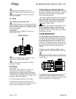
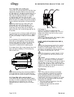
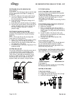
NF E 27 811
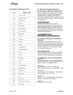
Provide sufficient space in the foundation to
accommodate the anchor bolts. If necessary, provide
concrete gullets.
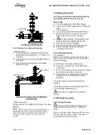
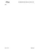
a) Levelling on the suction flange with a frame level
or on the discharge flange with a levelling
instrument .
b)
Admissible defect 0.5 mm for 1 meter (0.02 in
for 3.3 ft).
c)
Wedge under the pump.
Level
Frame
level
4.3 Piping
The user must verify that the equipment is
isolated from any external sources of vibration.
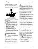
Protective covers are fitted to the
pipe connections to prevent foreign bodies entering
during transportation and installation. Ensure that
these covers are removed from the pump before
connecting any pipes.
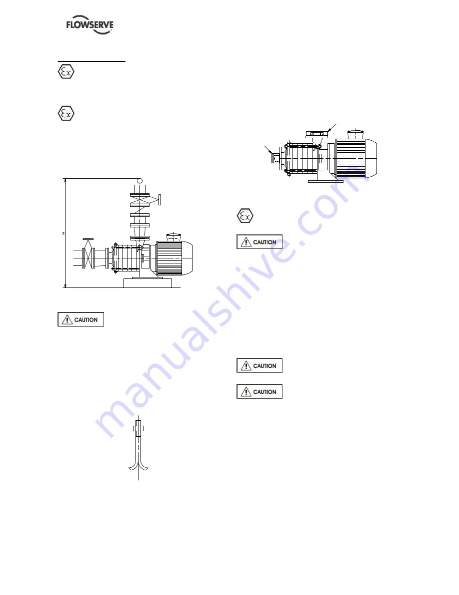
4.3.1 Suction and discharge piping
The dimensions of the pipes do not directly depend
on suction and discharge diameters of the pump:
a) First, choose a flow speed < 2 m/s (7 ft/s) at
suction, and about 3 m/s (10 ft/s) at discharge.
b)
Take into account the available NPSH, which
must be superior to the required NPSH of the
pump.
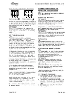
Never use pump as a support for
piping.
Do not mount expansion joints in
such a way that their force, due to internal pressure,
may act on the pump flange.
Maximum forces and moments allowed on the pump
flanges vary with the pump size and type. These
external strains may cause misalignment, heating of
the bearings, vibrations and the possible failure of
the pump casing.
When designing the pipework (§ 5.3.1, § 5.3.2, §
5.3.3) take necessary precautions in order not to
exceed maximum allowed strains.
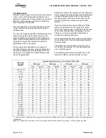
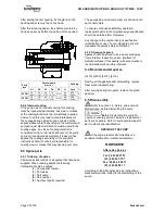
Forces and moments applied to the pump flanges
must never exceed the values shown in the following
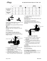
table:

