background image

UB USER INSTRUCTIONS  ENGLISH  71569247  07-04

Page 4 of 32

®

1  INTRODUCTION AND SAFETY

1.1  General


These Instructions must always be kept

close to the product's operating location or
directly with the product.

Flowserve products are designed, developed and
manufactured with state-of-the-art technologies in
modern facilities.  The unit is produced with great
care and commitment to continuous quality control,
utilising sophisticated quality techniques, and safety
requirements.

Flowserve is committed to continuous quality
improvement and being at service for any further
information about the product in its installation and
operation or about its support products, repair and
diagnostic services.

These instructions are intended to facilitate
familiarization with the product and its permitted use.
Operating the product in compliance with these
instructions is important to help ensure reliability in
service and avoid risks.  The instructions may not
take into account local regulations; ensure such
regulations are observed by all, including those
installing the product.  Always coordinate repair
activity with operations personnel, and follow all plant
safety requirements and applicable safety and health
laws and regulations.


These instructions should be read prior to

installing, operating, using and maintaining the
equipment in any region worldwide.  The
equipment must not be put into service until all
the conditions relating to safety, noted in the
instructions, have been met.

1.2  CE marking and approvals

It is a legal requirement that machinery and
equipment put into service within certain regions of
the world shall conform with the applicable CE
Marking Directives covering Machinery and, where
applicable, Low Voltage Equipment, Electromagnetic
Compatibility (EMC), Pressure Equipment Directive
(PED) and Equipment for Potentially Explosive
Atmospheres (ATEX).

Where applicable, the Directives and any additional
Approvals, cover important safety aspects relating to
machinery and equipment and the satisfactory
provision of technical documents and safety
instructions.  Where applicable this document
incorporates information relevant to these Directives

and Approvals.  To confirm the Approvals applying
and if the product is CE marked, check the serial
number plate markings and the Certification.  (See
section 9, 

Certification

.)

1.3  Disclaimer

Information in these User Instructions is believed to
be reliable.  In spite of all the efforts of Flowserve
Pump Division to provide sound and all necessary
information the content of this manual may appear
insufficient and is not guaranteed by Flowserve as
to its completeness or accuracy

.

Flowserve manufactures products to exacting
International Quality Management System Standards as
certified and audited by external Quality Assurance
organisations.  Genuine parts and accessories have
been designed, tested and incorporated into the
products to help ensure their continued product quality
and performance in use.  As Flowserve cannot test
parts and accessories sourced from other vendors the
incorrect incorporation of such parts and accessories
may adversely affect the performance and safety
features of the products.  The failure to properly select,
install or use authorised Flowserve parts and
accessories is considered to be misuse.  Damage or
failure caused by misuse is not covered by the
Flowserve warranty.  In addition, any modification of
Flowserve products or removal of original components
may impair the safety of these products in their use.

1.4  Copyright

All rights reserved.  No part of these instructions may
be reproduced, stored in a retrieval system or
transmitted in any form or by any means without prior
permission of Flowserve Pump Division.

1.5  Duty conditions

This product has been selected to meet the
specifications of your purchaser order.  The
acknowledgement of these conditions has been sent
separately to the Purchaser.  A copy should be kept
with these instructions.


The product must not be operated beyond

the parameters specified for the application.  If
there is any doubt as to the suitability of the
product for the application intended, contact
Flowserve for advice, quoting the serial number.

If the conditions of service on your purchase order are
going to be changed (for example liquid pumped,
temperature or duty) it is requested that the user seeks
the written agreement of Flowserve before start up.

Summary of Contents for Centrifugal Pump 8-UB-1

Page 1: ...e 8 UB 1 CENTRIFUGAL PUMP USER INSTRUCTIONS INSTALLATION OPERATION MAINTENANCE PCN 71569247 07 04 E supercedes 6176 6511 These instructions must be read prior to installing operating using and maintaining this equipment ...

Page 2: ...nections 16 4 8 Protection systems 16 5 COMMISSIONING START UP OPERATION AND SHUTDOWN 16 5 1 Pre commissioning procedure 16 5 2 Pump lubricants 17 5 3 Direction of rotation 17 5 4 Guarding 17 5 5 Priming and auxiliary supplies 17 5 6 Starting the pump 18 5 7 Running the pump 18 5 8 Stopping and shutdown 19 5 9 Hydraulic mechanical and electrical duty 19 PAGE 6 MAINTENANCE 20 6 1 General 20 6 2 Mai...

Page 3: ...ocation 4 1 12 Lubrication 5 2 and 6 2 3 Lubrication schedule 5 2 2 17 Maintenance 6 20 Maintenance schedule 6 2 20 Name nomenclature 3 2 11 Nameplate 1 7 1 8 Operating limits 3 4 1 11 Options 8 1 2 30 Ordering spare parts 6 3 1 22 Parts lists 8 29 Performance 3 4 11 Piping 4 5 13 PAGE Pre commissioning 5 1 16 Priming and auxiliary supplies 5 5 17 Protection systems 4 8 16 Reassembly 6 10 Assembly...

Page 4: ...his document incorporates information relevant to these Directives and Approvals To confirm the Approvals applying and if the product is CE marked check the serial number plate markings and the Certification See section 9 Certification 1 3 Disclaimer Information in these User Instructions is believed to be reliable In spite of all the efforts of Flowserve Pump Division to provide sound and all nec...

Page 5: ...regulations 1 6 3 Safety action This is a summary of conditions and actions to help prevent injury to personnel and damage to the environment and to equipment For products used in potentially explosive atmospheres section 1 6 4 also applies NEVER DO MAINTENANCE WORK WHEN THE UNIT IS CONNECTED TO POWER GUARDS MUST NOT BE REMOVED WHILE THE PUMP IS OPERATIONAL DRAIN THE PUMP AND ISOLATE PIPEWORK BEFO...

Page 6: ...art up operation and shutdown NEVER RUN THE PUMP DRY INLET VALVES TO BE FULLY OPEN WHEN PUMP IS RUNNING Running the pump at zero flow or below the recommended minimum flow continuously will cause damage to the pump and mechanical seal DO NOT RUN THE PUMP AT ABNORMALLY HIGH OR LOW FLOW RATES Operating at a flow rate higher than normal or at a flow rate with no back pressure on the pump may overload...

Page 7: ... could be installed in different hazarous atmospheres In this case the user is responsible for ensuring that the pump surface temperature does not exceed that permitted in the particular hazardous atmosphere If an explosive atmosphere exists during the installation do not attempt to check the direction of rotation by starting the pump unfilled Even a short run time may give a high temperature resu...

Page 8: ...osphere can result in a hazard the installation of a liquid detection device is recommended 1 6 4 7 Maintenance to avoid the hazard CORRECT MAINTENANCE IS REQUIRED TO AVOID POTENTIAL HAZARDS WHICH GIVE A RISK OF EXPLOSION The responsibility for compliance with maintenance instructions is with the plant operator To avoid potential explosion hazards during maintenance the tools cleaning and painting...

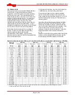
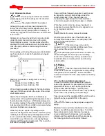
Page 9: ...res see the accompanying information sheets and manuals Typical sound pressure level dBA LpA at 1 m reference 20 µPa LwA sound power 1 pW where LpA 85 dBA 3550 r min 2900 r min 1750 r min 1450 r min Motor size and speed kW hp Pump and motor dBA Pump only dBA Pump and motor dBA Pump only dBA Pump and motor dBA Pump only dBA Pump and motor dBA Pump only dBA 0 55 0 75 71 88 66 83 64 81 62 79 64 81 62...

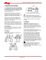
Page 10: ...e baseplate A crane must be used for all pump sets in excess of 25 kg 55 lb Fully trained personnel must carry out lifting in accordance with local regulations The driver weight is recorded on its nameplate or massplate 2 4 Storage Store the pump in a clean dry location away from vibration Leave piping connection covers in place to keep dirt and other foreign material out of pump casing Turn pump ...

Page 11: ... intervals 3 3 6 Seal housing The design enables one of a number of sealing options to be fitted 3 3 7 Shaft seal The mechanical seal s attached to the pump shaft seals the pumped liquid from the environment Gland packing may be fitted as an option 3 3 8 Driver The driver is normally an electric motor Different drive configurations may be fitted such as internal combustion engines turbines hydraul...

Page 12: ...ed and should be corrected by re shimming e If the pump is driven via a universal joint drive shaft there may be a requirement to offset the pump shaft with respect to the driver to optimize the universal joint drive shaft bearing life This offset will typically be in the range 0 to 4 degrees depending on shaft design Please consult the separate User Instructions before installation f Any support ...

Page 13: ...eries of couplings available Pumps with thick flanged non spacer couplings can be aligned by using a straight edge across the outside diameters of the coupling hubs and measuring the gap between the machined faces using feeler gauges measuring wedge or callipers When the electric motor has sleeve bearings it is necessary to ensure that the motor is aligned to run on its magnetic centreline Refer t...

Page 14: ...t pipe on the pump suction between the elbow and inlet flange See section 10 3 Reference 1 for more detail f Inlet strainers when used should have a net free area of at least three times the inlet pipe area g Do not install elbows at an angle other than perpendicular to the shaft axis Elbows parallel to the shaft axis will cause uneven flow h Except in unusual circumstances strainers are not recom...

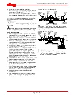
Page 15: ...aseplate See section 6 6 Fastener torques The bolt material must have a minimum yield strength of 600 N mm2 87 000 lb in 2 4 5 4 Discharge piping See section 4 5 2 for typical pipework design A non return valve should be located in the discharge pipework to protect the pump from excessive back pressure and hence reverse rotation when the unit is stopped Pipework reducers should have a maximum tota...

Page 16: ...ding any temperature earth leakage current and other protective devices as appropriate The identification nameplate should be checked to ensure the power supply is appropriate A device to provide emergency stopping must be fitted If not supplied pre wired to the pump unit the controller starter electrical details will also be supplied within the controller starter For electrical details on pump se...

Page 17: ...se to 55 C 131 F above ambient but should not exceed 95 C 204 F For most operating conditions a quality grease having a lithium soap base and NLGI consistency of No 2 or No 3 is recommended The drop point should exceed 175 C 350 F Never mix greases containing different bases thickeners or additives 5 3 Direction of rotation Ensure the pump is given the same rotation as the pump direction arrow cas...

Page 18: ...ust be adjusted evenly to give visible leakage and concentric alignment of the gland to avoid excess temperature If no leakage takes place the packing will begin to overheat If overheating takes place the pump should be stopped and allowed to cool before being re started When the pump is re started check to ensure leakage is taking place at the packed gland If hot liquids are being pumped it may b...

Page 19: ... duty and standby pumps are installed it is recommended that they are run alternately every week 5 8 Stopping and shutdown a Close the outlet valve but ensure that the pump runs in this condition for no more than a few seconds b Stop the pump c Switch off flushing and or cooling heating liquid supplies at a time appropriate to the process d For prolonged shut downs and especially when ambient temp...

Page 20: ...nd guard rails are required for maintenance they must be placed for easy access to areas where maintenance and inspection are to be carried out The positioning of these accessories must not limit access or hinder the lifting of the part to be serviced When air or compressed inert gas is used in the maintenance process the operator and anyone in the vicinity must be careful and have the appropriate...

Page 21: ...upling should be checked for correct alignment and worn driving elements Refer to the manuals of any associated equipment for periodic checks needed 6 2 3 Re lubrication Lubricant and bearing temperature analysis can be useful in optimizing lubricant change intervals In general however the following is recommended See section 5 2 1 for grease recommendations Regrease via grease nipples every 2 000...

Page 22: ...pare parts 6 3 1 Ordering of spares Flowserve keeps records of all pumps that have been supplied When ordering spares the following information should be quoted 1 Pump serial number 2 Pump size 3 Part name taken from section 8 4 Part number taken from section 8 5 Number of parts required The pump size and serial number are shown on the pump nameplate To ensure continued satisfactory operation repl...

Page 23: ...c Remove coupling guards and disconnect the coupling halves d Drain pump casing Remove any auxiliary piping if applicable e Release the copper lockwasher securing the coupling nut and remove the pump half coupling f Unbolt the glands seal covers from the casing If glands are split type remove completely g With a suitable punch drive out the two locating dowels which are used on the horizontal spli...

Page 24: ...th seals and bearing isolators should be inspected for damage but are normally non wearing parts and can be re used d Bearing seals are not totally leak free devices Oil from these may cause staining adjacent to the bearings 6 10 Assembly To assemble the pump consult the sectional drawings see section 8 Parts list and drawings Ensure threads gasket and O ring mating faces are clean Apply thread se...

Page 25: ...g distance piece and the distance piece is located up to the shaft shoulder j Fill both sides of bearing with grease k Fit the bearing lockwasher and tighten the bearing shaft nut l Peen a segment of the copper lockwasher over a flat on the bearing locknut m Slip casing rings loosely over the impeller hubs n Slide the bearing housings over the bearings Ensure bearings are located square in the bra...

Page 26: ...tted apply a small amount of silicon rubber sealant along the horizontal joint line on the stuffing box face and fit seal cover complete with gasket or O ring Take care not to damage O ring if fitted and locate cover squarely on stuffing box face f Torque up seal cover bolts and check shaft sleeve does not rub on seal cover or stationary seal seat bore Ensure any spare holes in mechanical seal cov...

Page 27: ...ly clogged Clean foot valve z z z z z z z z z z z z z z z z Inlet of suction pipe insufficiently submerged Check cut out system design z z z z z z z z z z z z Total head of system higher than differential head of pump Check discharge head and head losses in discharge pipe at the valve settings Check back pressure is not too high z z z z Total head of system lower than pump design head Throttle at ...

Page 28: ...e resulting in vibration Check and consult Flowserve z z z z z z z z z z z z Abrasive solids in liquid pumped Check and consult Flowserve z z z z z z z z Mechanical seal was run dry Check mechanical seal condition and source of dry running and repair z z z z z z z z z z z z z z z z z z z z z z z z Internal misalignment due to improper repairs causing impeller to rub Check method of assembly possib...

Page 29: ...ring locknut 4 Ball bearing thrust 5 Shaft collar 6 Gland 7 Lantern ring 8 Gland packing 9 Casing upper half 10 Casing lower half 11 Gasket horizontal split 12 Casing wear ring 13 Diaphragm plate 14 Diaphragm bush 15 Impeller first stage 15A Impeller second stage 16 Key impeller 17 Seal pipe assembly 18 Shaft sleeve 19 Shaft nut 20 Bearing bracket Drive end 20A Bearing bracket Non drive end 21 Soc...

Page 30: ...g a 39 Cartridge seal assembly 40 Impeller nut 45 Impeller wear ring 46 Socket head screw for 45 a When fitted depends on type of mechanical seal 8 2 General arrangement drawing The typical general arrangement drawing and any specific drawings required by the contract will be sent to the Purchaser separately unless the contract specifically calls for these to be included into the User Instructions...

Page 31: ...ginal format If further copies of these are required they should be obtained from the supplier for retention with these User Instructions 10 2 Change notes If any changes agreed with Flowserve Pump Division are made to the product after its supply a record of the details should be maintained with these User Instructions 10 3 Additional sources of information Reference 1 NPSH for Rotordynamic Pumps...

Page 32: ...lowserve Corporation Pump Division 6840 Wynnwood Lane Houston Texas 77008 USA Tel 1 713 803 4434 Fax 1 713 803 4497 Asia Pacific Flowserve Pte Ltd Pump Division 200 Pandan Loop 06 03 04 Pantech 21 Singapore 128388 Tel 65 775 3003 Fax 65 779 4607 Visit our web site at www flowserve com Your Flowserve factory contact Flowserve Pumps Limited PO Box 17 Newark Notts NG24 3EN United Kingdom Telephone 24...

Reviews: