MHP-TN USER INSTRUCTIONS ENGLISH 71576313 - 02/07
Page 20 of 28
flowserve.com
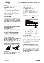
The example (N) value is given for the preferred
operating flow region (typically this may extend to
70 to 120 % of the pump best efficiency point);
outside the preferred flow region the actual
vibration experienced may be multiplied by up to 2.
These standard values can vary with the rotational
speed and the power absorbed by the pump. For
any special case, do not hesitate to consult us.
Measuring vibration at regular intervals will then
show any deterioration in pump or system
operating conditions.
Vibration Velocity - unfiltered
Horizontal
Configuration
mm/s (in./s) r.m.s.
Normal
N
5.6 (0.22)
Alarm
N
x 1.25
7.1 (0.28)
Shutdown Trip
N
x 2.0
11.2 (0.44)
5.5.5 Stop/start frequency
Pump sets are normally suitable for the number of
equally spaced stop/starts per hour shown in the
table below. Check actual capability of the driver
and control/starting system before commissioning.
Motor rating kW (hp)
Maximum stop/starts
per hour
Up to 15 (20)
15
Between 15 (20) and 90 (120)
10
90 (120) to 150 (200)
6
Above 150 (200)
Refer
Where duty and standby pumps are installed it is
recommended that they are run alternately every
week.
5.6 Stopping and shutdown
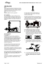
According to hydraulic conditions of
the installation and its automation degree, stop
and restart procedures can have different forms.
Nevertheless all of them must respect imperatively
the following rules:
5.6.1 Stopping < 1 hour
a) Isolate motor.
b)
Avoid reverse rotation of the pump.
c)
Make sure that the discharge line pressure
does not reach the foot valve.
5.6.2 Stopping < 1 month
a) Isolate motor.
b)
Avoid reverse rotation of the pump.
c)
Make sure that the discharge line pressure
does not reach the foot valve.
d)
Close the outlet valve. Eventually close the
inlet valve.
e) Switch off external power supply,
flushing/quench, cooling liquid.
5.6.3 Shutdown > 1 month
a)
Isolate motor.
b)
Avoid reverse rotation of the pump.
c)
Make sure that the discharge line pressure
does not reach the foot valve.
d)
Close the outlet valve. Eventually close the
inlet valve.
e)
Switch off external power supply,
flushing/quench, cooling liquid.
f)
Keep the pump fully filled with water. In case
of pumped liquid other than water, drain the
pump entirely.
g)
Turn once per week the pump shaft of one or
two turns.
h)
Never restart the pump without carrying out
the verifications recommended before starting
(see § 5.4.1).
When ambient temperatures are
likely to drop below freezing point, the pump and
any cooling and flushing arrangements must be
drained or otherwise protected.
5.6.4 Restarting in continuous running
a)
Ensure that the pump is completely full of
liquid.
b)
Ensure a continuous supply with a sufficient
available NPSH.
c)
Ensure a backpressure so that the motor
power is not in excess.
d)
Respect the starting frequency
imposed by the motor manufacturer.
e)
Protect the pump against water hammer
when stopping or starting.
5.7 Hydraulic, mechanical and
electrical duty
This product has been supplied to meet the
performance specifications of your purchase order,
however it is understood that during the life of the
product these may change. The following notes
may help the user decide how to evaluate the
implications of any change. If in doubt contact your
nearest Flowserve office.
5.7.1 Specific gravity (SG)
Pump capacity and total head in meters (feet) do
not change with SG, however pressure displayed
on a pressure gauge is directly proportional to SG.
Power absorbed is also directly proportional to SG.
It is therefore important to check that any change
in SG will not overload the pump driver or over-
pressurize the pump.
5.7.2 Viscosity
For a given flow rate the total head reduces with
increased viscosity and increases with reduced
viscosity.

