background image

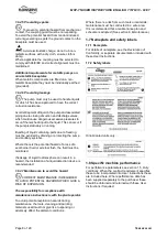
MHP-TN USER INSTRUCTIONS ENGLISH 71576313 - 02/07

Page 21 of 28

flowserve.com

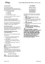
Also for a given flow rate the power absorbed
increases with increased viscosity, and reduces
with reduced viscosity. It is important that checks
are made with your nearest Flowserve office if
changes in viscosity are planned.

5.7.3 Pump speed

Changing pump speed effects flow, total head,
power absorbed, NPSH

R

, noise and vibration.

Flow varies in direct proportion to pump speed,
head varies as speed ratio squared and power
varies as speed ratio cubed. The new duty,
however, will also be dependent on the system
curve.

If increasing the speed, it is important therefore to
ensure the maximum pump working pressure is
not exceeded, the driver is not overloaded, NPSH

A

> NPSH

R

, and that noise and vibration are within

local requirements and regulations.

5.7.4 Net positive suction head (NPSH

A

)

NPSH available (NPSH

A

) is the head available at

the impeller inlet, above the vapor pressure of the
pumped liquid.

NPSH required (NPSH

R

) is the minimum head

required at the impeller inlet, above the vapor
pressure of the pumped liquid, to avoid excessive
cavitation and extreme performance degradation.

It is important that NPSH

A

> NPSH

R

. The margin

between NPSH

A

> NPSH

R

should be as large as

possible.

If any change in NPSH

A

is proposed, ensure these

margins are not significantly eroded. Refer to the
pump performance curve to determine exact
requirements particularly if flow has changed.

If in doubt please consult your nearest Flowserve
office for advice and details of the minimum
allowable margin for your application.

5.7.5 Pumped flow

Flow must not fall outside the minimum and
maximum continuous safe flow shown on the
pump performance curve and or data sheet.

5.8 Pumps for Food Use or Potable
Water

If the pump has not been specifically ordered for a
food or drinking water application it must not be
used for these types of applications. If it has been
ordered for this type of application the following
recommendations are to be followed.

5.8.1 Cleaning prior to operation

Pumps that are to be used for a food or drinking
water application should be cleaned before being
put into initial operation and after the installation of
spare parts that are in contact with the liquid.

Cleaning once the pump has been commissioned
will depend on the application and operating
conditions. The user must ensure that the cleaning
procedures are suitable for the application and
operating conditions, and local regulations.

6 MAINTENANCE

6.1 General

If a belt drive is used, the assembly and

tension of the belts must be verified during regular
maintenance procedure.

In dirty or dusty environments, regular checks

must be made and dirt removed from areas around
close clearances, bearing housings and motors.

It is the plant operator's responsibility to

ensure that all maintenance, inspection and
assembly work is carried out by authorized and
qualified personnel who have adequately
familiarized themselves with the subject matter by
studying this manual in detail (see also section
1.6.2).

Any work on the machine must be performed when
it is at a standstill. It is imperative that the
procedure for shutting down the machine is
followed, as described in section 5.6.

On completion of work all guards and safety
devices must be re-installed and made operative
again. Before restarting the machine, the relevant
instructions listed in section 5,

Commissioning,

start up, operation and shut down

must be

observed.

Oil and grease leaks may make the ground
slippery. Machine maintenance must always
begin and finish by cleaning the ground and
the exterior of the machine.

If platforms, stairs and guardrails are required for
maintenance, they must be placed for easy access
to areas where maintenance and inspection are to
be carried out. The positioning of these
accessories must not limit access or hinder the
lifting of the part to be serviced.

Summary of Contents for Centrifugal Pump M-TN

Page 1: ...fugal pump Single stage axial suction vertical discharge type centrifugal pump PCN 71576313 02 07 E Installation Operation Maintenance These instructions must be read prior to installing operating using and maintaining this equipment ...

Page 2: ... 6 Electrical connections 16 4 7 Final shaft alignment check 17 4 8 Protection systems 17 5 COMMISSIONING START UP OPERATION AND SHUTDOWN 17 5 1 Direction of rotation 17 5 2 Guarding 17 5 3 Priming and auxiliary supplies 17 5 4 Starting the pump 18 5 5 Running the pump 19 5 6 Stopping and shutdown 20 5 7 Hydraulic mechanical and electrical duty 20 5 8 Pumps for Food Use or Potable Water 21 Page 6 ...

Page 3: ...al and electrical duty 5 7 20 Inspection 6 2 2 and 6 2 3 22 Installation 4 13 Internal coating 6 2 5 23 Lifting 2 3 10 Location 4 1 13 Maintenance 6 21 Maintenance schedule 6 2 22 Nomenclature 3 2 11 Nameplate 1 7 1 8 Operating limits see 3 1 12 Ordering spare parts 6 3 1 24 Parts lists 8 2 27 Piping 4 5 15 Protection systems 4 8 17 Pump masses 2 2 2 10 Receipt and unpacking 2 1 10 Recommended spa...

Page 4: ...ere applicable this document incorporates information relevant to these Directives and Approvals To confirm the Approvals applying and if the product is CE marked check the serial number plate markings and the Certification See section 9 Certification 1 3 Disclaimer Information in these User Instructions is believed to be reliable In spite of all the efforts of Flowserve Corporation to provide sou...

Page 5: ...ons and health and safety personnel and follow all plant safety requirements and applicable safety and health laws and regulations 1 6 3 Safety action This is a summary of conditions and actions to prevent injury to personnel and damage to the environment and to equipment For products used in potentially explosive atmospheres section 1 6 4 also applies NEVER DO MAINTENANCE WORK WHEN THE UNIT IS CO...

Page 6: ...stability and cavitation vibration 1 6 4 Products used in potentially explosive atmospheres The following instructions for pumps and pump units when installed in potentially explosive atmospheres must be followed to help ensure explosion protection The terminology and procedures ensure that the installed pump is in compliance with the European Directive 94 9 EC known as the ATEX Directive which is...

Page 7: ...d when the liquid temperature varies and the pump could be installed in different hazardous atmospheres In this case the user is responsible for ensuring that the pump surface temperature does not exceed that permitted in the particular hazardous atmosphere If an explosive atmosphere exists during the installation do not attempt to check the direction of rotation by starting the pump unfilled Even...

Page 8: ...nd ancillary systems Where there is the potential hazard of a loss of a seal barrier fluid or external flush the fluid must be monitored If leakage of liquid to atmosphere can result in a hazard the installation of a liquid detection device is recommended 1 6 4 7 Maintenance to avoid the hazard CORRECT MAINTENANCE IS REQUIRED TO AVOID POTENTIAL HAZARDS WHICH GIVE A RISK OF EXPLOSION The responsibi...

Page 9: ... Flowserve or a noise specialist if assistance is required in combining the values It is recommended that where exposure approaches the prescribed limit then site noise measurements should be made The values are in sound pressure level LpA at 1 m 3 3 ft from the machine for free field conditions over a reflecting plane For estimating sound power level LWA re 1 pW then add 17 dBA to the sound press...

Page 10: ...ng Boxes crates pallets or cartons may be unloaded using forklift vehicles or slings dependent on their size and construction See 2 3 1 for positioning of slings To lift heavy pieces above 25 kg 55 lb use a winch adapted to the mass and in accordance with the current local regulations To lift machines or pieces with one or several suspension rings only use hooks and chains in compliance with the l...

Page 11: ...azardous substances or toxic fluid are disposed of safely and that the correct personal protective equipment is used The safety specifications must be in accordance with the current regulations at all times 3 PUMP DESCRIPTION 3 1 Configurations The centrifugal motor pump is designed for the pumping of cold water or all clear liquids which are not solid and liquid mixtures non corrosive non abrasiv...

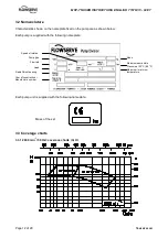
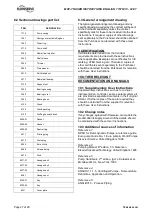
Page 12: ...ow Each pump is supplied with the following nameplate Each pump unit is supplied with the following nameplate Mass of the set 3 3 Coverage charts 3 3 1 2900 min 1 50 Hz coverage charts Q H Pump type Speed of rotation Flow rate Year of construction Manufacture number Head Radial thrust bearing Mass Maximum admissible Pressure at 20 C 68 F Maximum minimum temperature ...

Page 13: ...distorted or pulled down onto the surface of the foundation but should be supported to maintain the original alignment Anchor bolts must be in accordance with the foot bolt holes Use anchor bolts of accepted standards and sufficient to ensure a secure fitting in the foundation Particularly this applies to individual plates where the anchor bolts have to withstand the driving torque NF E 27 811 Pro...

Page 14: ...ecked immediately 4 4 2 Alignment methods Ensure pump and driver are isolated electrically and the half couplings are disconnected Ensure that the pump pipework suction and discharge is disconnected The alignment MUST be checked Although the pump will have been aligned at the factory it is most likely that this alignment will have been disturbed during transportation or handling If necessary align...

Page 15: ... due to internal pressure may act on the pump flange Maximum forces and moments allowed on the pump flanges vary with the pump size and type These external strains may cause misalignment hot bearings worn couplings vibrations and the possible failure of the pump casing When designing the pipes 4 5 2 1 4 5 2 2 4 5 3 1 take necessary precautions in order not to exceed maximum allowed strains Forces ...

Page 16: ...ometer pressure gauge can be connected on the piping Control manometer Do not tighten flanges before the final check see 4 5 4 4 5 4 Final checks a Check the tightening of anchor bolts Tighten them if necessary b Check that protective covers on suction and discharge flanges are removed c Check that holes of piping flanges are parallel and correspond to those of the pump d Tighten suction and disch...

Page 17: ...ystem is installed To prevent excessive surface temperatures at bearings it is recommended that temperature or vibration monitoring are carried out See sections 5 5 3 and 5 5 4 If a defect of cooling can lead to temperature higher than those acceptable a system of cooling surveillance must be installed Except when explicitly required by the customer in the specifications when a possibility of reve...

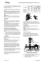
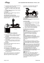
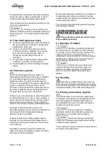
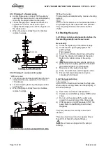
Page 18: ...foot valve seat and shutter 5 4 Starting the pump 5 4 1 Bring controls and preparation before the first starting and after each service call Necessarily a Check the tightening of the different plugs b Check that the gland lightly tightens the packing rings c Risk of seal ring overheating d Check the direction of rotation of the motor Refer to the rotation arrow of the pump e Install all protection...

Page 19: ... WHEN THE PUMP IS RUNNING If hot or freezing components of the machine can present a danger to operators they must be shielded to avoid accidental contact If a 100 protection is not possible the machine access must be confined to the maintenance staff only If the temperature is greater than 80 C 176 F a warning plate must be clearly placed on the pump It is strictly forbidden to open switch cupboa...

Page 20: ...the inlet valve e Switch off external power supply flushing quench cooling liquid 5 6 3 Shutdown 1 month a Isolate motor b Avoid reverse rotation of the pump c Make sure that the discharge line pressure does not reach the foot valve d Close the outlet valve Eventually close the inlet valve e Switch off external power supply flushing quench cooling liquid f Keep the pump fully filled with water In ...

Page 21: ...tion it must not be used for these types of applications If it has been ordered for this type of application the following recommendations are to be followed 5 8 1 Cleaning prior to operation Pumps that are to be used for a food or drinking water application should be cleaned before being put into initial operation and after the installation of spare parts that are in contact with the liquid Clean...

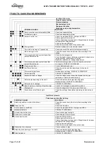
Page 22: ...ty condition is in the safe operating range for the pump i Check vibration noise level and surface temperature at the bearings to confirm satisfactory operation j Check the tightness of the connections k Check dirt and dust is removed from areas around close clearances bearing housings and motors l Check coupling alignment and re align if necessary m Verify the correct operation of the system The ...

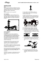
Page 23: ...al diameter is lightly tightened and there is an initial gap between the sleeve and the packing ring For that purpose wind the packing helically around the shaft sleeve or a chuck of the same diameter Take precautions to avoid damaging sleeve Example of straight cut Example of bevel cut Ensure a tightening on the stuffing box housing and not on the sleeve SETTING OF PACKING Follow the instructions...

Page 24: ... any removal from the shaft c After serving during two years replace the gland packing 6 5 Disassembly Refer to section 1 6 Safety and section 6 Maintenance before dismantling the pump Before dismantling the pump for overhaul ensure genuine Flowserve replacement parts are available Refer to sectional drawings for part numbers and identification REPAIR OF THE PUMP If the pump presents abnormalities...

Page 25: ...and discharge pipes valves back pressure Worn wear ring surfaces Foresee pump mending CONSULT FLOWSERVE Seizure jamming CONSULT FLOWSERVE Excessive strains on flanges Check the flange connections and eliminate strains pipe positioning or elastic sleeves mounting Defective gland packing on the shaft Check and replace all the gland packing parts Mechanical seal CONSULT FLOWSERVE Defective motor bear...

Page 26: ...MHP TN USER INSTRUCTIONS ENGLISH 71576313 02 07 Page 26 of 28 flowserve com 8 PARTS LIST AND DRAWINGS 8 1 Sectional drawings 9331 ...

Page 27: ...s determined from the Contract requirements are provided with these instructions where applicable Examples are certificates for CE marking ATEX marking etc If required copies of other certificates sent separately to the Purchaser should be obtained from the Purchaser for retention with these User Instructions 10 OTHER RELEVANT DOCUMENTATION AND MANUALS 10 1 Supplementary User Instructions Suppleme...

Page 28: ...4 Pantech 21 Singapore 128388 Telephone 65 6775 3003 Fax 65 6779 4607 Local Flowserve factory representatives North America Flowserve Pump Division 5310 Taneytown Pike PO Box 91 Taneytown MD 21787 0091 USA Telephone 1 410 756 2602 Customer Service FAX 1 410 756 2615 Parts inquiry Order PH 1 800 526 3569 South America Flowserve do Brasil Ltda Av Don Helder Camara 5451 20771 001 Rio de Janerio Brasi...

Reviews: