background image

DMX/DMXD/DMXH/DMXDH USER INSTRUCTIONS  ENGLISH  71569282 - 10/09

Page 5 of 60

overheating of the pump, instability and cavitation/
vibration.

Do not run the pump at abnormally

high or low flow rates. Operating at a flow rate higher
than normal or at a flow rate with no backpressure on
the pump may overload the motor and cause pump
cavitation.

Never do maintenance work when

the unit is connected to power.

When the pump is handling hazardous

liquids care must be taken to avoid exposure to
the liquid by appropriate sitting of the pump,
limiting personnel access and by operator
training.  If the liquid is flammable and/or
explosive, strict safety procedures must be
applied.

HANDLING COMPONENTS

Many precision parts have sharp corners and the
wearing of appropriate safety gloves and
equipment is required when handling these
components.  To lift heavy pieces above 25 kg (55
lb) use an appropriate crane for the mass and in
accordance with current local regulations.

Coupling guards must not be removed while

the pump is operational.

THERMAL SHOCK

Rapid changes in the temperature of the liquid
within the pump will cause thermal shock, which
can result in damage or breakage of components
and should be avoided.

HOT (and cold) PARTS

If hot or freezing components or auxiliary heating
supplies can present a danger to operators and
persons entering the immediate area action must
be taken to avoid accidental contact.  If complete
protection is not possible, the machine access
must be limited to maintenance staff only, with
clear visual warnings and indicators to those
entering the immediate area.  Note: bearing
housings must not be insulated and drive motors
and bearings may be hot.

If the temperature is greater than 68 °C (154°F) or
below -5 °C (20 °F) in  a restricted zone, or
exceeds local regulations, action as above shall
be taken.

1.6.4 

Products used in potentially explosive
atmospheres

Measures are required to:

Avoid excessive temperature

Prevent the build up of explosive mixtures

Prevent the generation of sparks

Prevent leakages

Maintain the pump to avoid hazard

The following instructions for pumps and pump units
when installed in potentially explosive atmospheres
must be followed to help ensure explosion protection.
Both electrical and non-electrical equipment must
meet the requirements of European Directive
94/9/EC.

1.6.4.1 

Scope of compliance

Use equipment only in the zone for which it is

appropriate.  Always check that the driver, drive
coupling assembly, seal and pump equipment are
suitably rated and/or certified for the classification of
the specific atmosphere in which they are to be
installed.

Where Flowserve has supplied only the bare shaft
pump, the Ex rating applies only to the pump.  The
party responsible for assembling the ATEX pump set
shall select the coupling, driver and any additional
equipment, with the necessary CE Certificate/
Declaration of Conformity establishing it is suitable for
the area in which it is to be installed.

The output from a variable frequency drive (VFD) can
cause additional heating effects in the motor and so,
for pumps sets with a VFD, the ATEX Certification for
the motor must state that it is covers the situation
where electrical supply is from the VFD.  This
particular requirement still applies even if the VFD is
in a safe area.

1.6.4.2 

Marking

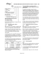
An example of ATEX equipment marking is shown
below.  The actual classification of the pump will be
engraved on the nameplate.

Summary of Contents for DMX

Page 1: ...ute Multistage single double suction horizontally split volute type centrifugal pumps type centrifugal pumps PCN 71569282 10 09 E PCN 71569282 10 09 E Original instructions Original instructions BALL BALL CONFIGURATION BALL BALL CONFIGURATION These instructions must be read prior to installing These instructions must be read prior to installing operating using and maintaining the operating using a...

Page 2: ... 4 8 Protection system Protection systems s 27 27 5 5 COMMISSIONING START UP OPERATION COMMISSIONING START UP OPERATION AND SHUTDO AND SHUTDOWN WN 28 28 5 1 5 1 Precommissioning Precommissioning procedure procedure 28 28 5 2 5 2 Pump Pump lubricants lubricants 29 29 5 3 5 3 Impeller wearring Impeller wearring clearance clearance 31 31 5 4 5 4 Direction of rotation 31 Direction of rotation 31 5 5 5...

Page 3: ...es ATEX Atmospheres ATEX Where applicable the Directives and any additional Where applicable the Directives and any additional Approvals cover important safety aspects relating to Approvals cover important safety aspects relating to machinery and equipment and the satisfactory machinery and equipment and the satisfactory provision of technical documents and safety provision of technical documents ...

Page 4: ...assembly process 1 6 2 Personnel qualification and training All personnel involved in the operation installation inspection and maintenance of the unit must be qualified to carry out the work involved If the personnel in question do not already possess the necessary knowledge and skill appropriate training and instruction must be provided If required the operator may commission the manufacturer su...

Page 5: ...s must not be insulated and drive motors and bearings may be hot If the temperature is greater than 68 C 154 F or below 5 C 20 F in a restricted zone or exceeds local regulations action as above shall be taken 1 6 4 Products used in potentially explosive atmospheres Measures are required to Avoid excessive temperature Prevent the build up of explosive mixtures Prevent the generation of sparks Prev...

Page 6: ...liquid temperature is with the plant operator If an explosive atmosphere exists during the installation do not attempt to check the direction of rotation by starting the pump unfilled Even a short run time may give a high temperature resulting from contact between rotating and stationary components Where there is any risk of the pump being run against a closed valve generating high liquid and casi...

Page 7: ...ed by draining or protecting the pump and ancillary systems Where there is the potential hazard of a loss of a seal barrier fluid or external flush the fluid shall be monitored If leakage of liquid to atmosphere can result in a hazard then a liquid detection device shall be installed 1 6 4 7 Maintenance to avoid the hazard CORRECT MAINTENANCE IS REQUIRED TO AVOID POTENTIAL HAZARDS WHICH GIVE A RIS...

Page 8: ... determine the estimated sound pressure levels SPL expressed in dBA dB for DMX DMXD DMXH DMXDH pumps The values shown have been derived from actual noise test data and are based on the following conditions a Equipment is located in a free field above a reflecting plane in which the reduction in noise level in all directions is 6 dB in each octave band for each doubling of distance b Background noi...

Page 9: ... Test Method for Compressive Test Method for Compressive Strength of Hydraulic Cement Mortars Modified Strength of Hydraulic Cement Mortars Modified ASTM C 469 87a ASTM C 469 87a Test Method for Static Modulus of Test Method for Static Modulus of Elasticity and Poisson s Ratio of Concrete in Elasticity and Poisson s Ratio of Concrete in Compression Compression ASTM C 496 90 ASTM C 496 90 Test Meth...

Page 10: ...prevent turning Foundation complete description Foundation complete description b b Build a Build a dam around dam around the foundation the foundation to to contain contain grout materials grout materials Before grouting check level of Before grouting check level of machined pads of baseplate in both directions and machined pads of baseplate in both directions and perform a rough shaft coupling a...

Page 11: ...er the edges of the baseplate evenly evenly Pour grout until level reaches top of dam Pour grout until level reaches top of dam Allow drying sufficiently to prevent grout from Allow drying sufficiently to prevent grout from overflowing while completing the remaining grouting overflowing while completing the remaining grouting Do not vibrate baseplate when grouting Do not vibrate baseplate when gro...

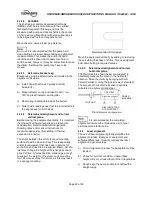
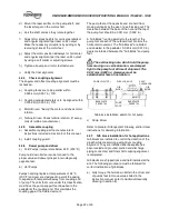
Page 12: ... Offset misalignment Combined misalignment 4 4 1 2 Alignment methods The following methods may be used to align equipment train The methods a and b are dial indicator based a Rim and face alignment Rim and face alignment b Reverse rim indicator alignment Reverse rim indicator alignment c Laser alignment 4 4 2 Dial indicator based alignment 4 4 2 1 Check soft foot Soft foot can affect the alignment...

Page 13: ...ansion is a factor The shims between the motor feet and mounting surface should be clean and dry This is especially critical for equipment that has been in service for some time and need to be realigned Water dirt and rust may change the height of the shim pack over a period of time Shims should be made large enough to support the weight of the motor on its mounting foot Do not use many thin shims...

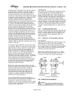
Page 14: ...s classification must have the pump support feet dowelled to the pedestal at the coupling end This maintains the coupling gap at the desired amount The pump feet at the opposite end are held from moving vertically by the use of a self locking nut The clearance between the base of the nut and the top of the pump foot should be 0 051 mm 0 002 in A Gib Block running parallel to the length of the pump...

Page 15: ...red to prevent cavitation When dirt and scale have been removed from the system as indicated by no further change in pressure drop across the strainer with time the start up strainer may be removed or the screen may be replaced with one having larger openings If a permanent strainer will be used during normal operation the pressure differential needs to be monitored on a continuous basis If a perm...

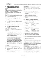
Page 16: ...ump uncoupled 4 7 Final shaft alignment check After connecting piping to the pump rotate the shaft several times by hand to ensure there is no binding and all parts are free Recheck the coupling alignment as previously described to ensure no pipe strain If pipe strain exists correct piping Refer to section entitled shaft coupling alignment and perform a coupling alignment check as outlined This ch...

Page 17: ...rap to make sure it turns freely d Ensure that the mechanical seal is properly assembled and tightened Most cartridge seals are equipped with a spacer between the gland plate and drive collar This spacer must be removed before starting unit e Ensure coupling is properly aligned and lubricated and pump and driver are properly doweled Refer to shaft coupling alignment procedure f Ensure coupling gua...

Page 18: ... Ensure all electrical hydraulic pneumatic sealant and lubrication systems as applicable are connected and operational Ensure the inlet pipe and pump casing are completely full of liquid before starting continuous duty operation 5 7 Starting the pump 5 7 1 Initial start up See 5 1 3 Initial start up procedure 5 7 2 Normal start up The starting procedure to be followed for normal start up is the sa...

Page 19: ...ppropriate lubrication can result in overheating of the bearings bearing failures pump seizures and actual breakdown of the equipment exposing operating personnel to injury 5 9 Stopping and shutdown If motor driven de energize driver circuit If turbine driven stop turbine driven pumps by manually tripping the overspeed trip If pump stops abruptly when driver is shut down investigate for pump bindi...

Page 20: ...eds other than of the original condition refer to Flowserve for recommendations 5 10 4 Net positive suction head NPSH Any liquid hot or cold must be forced into the impeller of the pump without vaporization by the pressure of the vessel from which the pump takes its suction The head of liquid necessary to force the required flow into the pump is called the Net Positive Suction Head This value more...

Page 21: ...heated it will have to be pushed towards the center of the pump the split rings 2531 removed and quickly pulled from the end of the shaft The shaft is step machined at each impeller fit to ease the disassembly process It is recommended that each impeller be marked with stage number to insure proper reassembly 6 6 8 Heating impellers for removal a Apply heat torch with fine tip to periphery outer 3...

Page 22: ... If new casing rings are used make sure that they seat in both the upper and lower half casing and that the anti rotation device is properly located in its respective lower half casing fit The use of a scraper on the ring to casing fit will help to fit the ring to the casing e Using a torch could change the metallurgy of the rings if too much heat is applied Removing impellers with torch is accept...

Page 23: ...ings to facilitate mounting Bearings still wrapped in their original intimate wrap are placed on a shelf in a temperature controlled oven A temperature of 66 C 150 F for one half hour should be sufficient b When bearings are installed on shaft or journal sleeve make sure bearing is installed squarely and is firmly seated Hold bearing in place until it has cooled sufficiently so that it will not mo...

Page 24: ...DMX DMXD DMXH DMXDH USER INSTRUCTIONS ENGLISH 71569282 10 09 Page 58 of 60 NOTES ...

Page 25: ...DMX DMXD DMXH DMXDH USER INSTRUCTIONS ENGLISH 71569282 10 09 Page 59 of 60 NOTES ...

Page 26: ...3 4434 Fax 1 713 803 4497 Asia Pacific Flowserve Pte Ltd 10 Tuas Loop Singapore 637345 Telephone 65 6771 0600 Fax 65 6779 4607 Your local Flowserve representative To find your local Flowserve representative please use the Sales Support Locator System found at www flowserve com Your Flowserve factory contacts Flowserve Corporation Parallelweg 6 4878 AH Etten Leur The Netherlands Telephone 31 76 502...

Reviews: