DURCO MARK 3 ISO FRAME MOUNTED ENGLISH 85392719 06-12
Page 13 of 52
flowserve.com
A fully confined gasket forms the seal between the
pump casing and the cover.
The cover designs provide improved performance of
mechanical seals.
The design enables one of a number of sealing
options to be fitted.
3.3.8
Shaft seal
The mechanical seal(s) attached to the drive shaft
seals the pumped liquid from the environment. Gland
packing may be fitted as an option, except on the P
self-primer casing.
3.3.9
Driver
The driver is normally an electric motor. Different drive
configurations may be fitted such as internal combustion
engines, turbines, hydraulic motors, and driving via
couplings, belts, gearboxes, drive shafts etc.
3.3.10 IPS Beacon
The pump is fitted with a temperature and vibration
monitor as standard. For additional information see
the User Instructions which are supplied separately.
3.3.11 Accessories
Accessories may be fitted when specified by the
customer.
Fan cooling is available for high temperature operation.
(This is a fan fitted within the coupling guard to blow
cooling air over the bearing housing and shaft.)
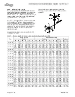
3.4 Performance and operating limits
This product has been selected to meet the
specifications of the purchase order. See section 1.5.
The following data is included as additional
information to help with your installation. It is typical,
and factors such as temperature, materials, and seal
type may influence this data. If required, a definitive
statement for your particular application can be
obtained from Flowserve.
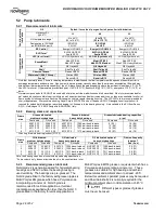
3.4.1
Operating limits
Normal maximum ambient temperature:
+40 ºC (104 ºF).
Normal minimum ambient temperature:
-20 ºC (-4 ºF).
Maximum pump speed: refer to the nameplate.
4
INSTALLATION
Equipment operated in hazardous locations
must comply with the relevant explosion protection
regulations. See section 1.6.4, Products used in
potentially explosive atmospheres.
4.1 Location
The pump should be located to allow room for access,
ventilation, maintenance and inspection with ample
headroom for lifting and should be as close as
practicable to the supply of liquid to be pumped. Refer
to the general arrangement drawing for the pump set.
4.2 Part assemblies
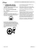
On baseplated pump sets the coupling elements are
supplied loose. It is the responsibility of the installer
to ensure that the pump set is finally lined up as
detailed in section 4.5.2, Alignment methods.
4.3 Foundation
There are many methods of installing
pump units to their foundations. The correct method
depends on the size of the pump unit, its location and
noise and vibration limitations. Non-compliance with
the provision of correct foundation and installation
may lead to failure of the pump and, as such, would
be outside the terms of the warranty.
Ensure the following are met:
a) The baseplate should be mounted onto a firm
foundation, either an appropriate thickness of
quality concrete or sturdy steel framework. (It
should NOT be distorted or pulled down onto the
surface of the foundation, but should be
supported to maintain the original alignment.)
b) Install the baseplate onto packing pieces evenly
spaced and adjacent to foundation bolts.
c) Level with shims between baseplate and packing
pieces.
d) The pump and driver have been aligned before
dispatch however the alignment of pump and motor
half coupling must be checked. If this is incorrect, it
Summary of Contents for Durco Mark 3
Page 49: ...DURCO MARK 3 ISO FRAME MOUNTED ENGLISH 85392719 06 12 Page 49 of 52 flowserve com Notes ...
Page 50: ...DURCO MARK 3 ISO FRAME MOUNTED ENGLISH 85392719 06 12 Page 50 of 52 flowserve com Notes ...
Page 51: ...DURCO MARK 3 ISO FRAME MOUNTED ENGLISH 85392719 06 12 Page 51 of 52 flowserve com Notes ...


