background image


ERPN-M USER INSTRUCTIONS ENGLISH 02-08


Page 31 of 37 

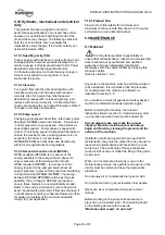
7.3.3 Flushing plan no. 21S according to API 685 


Flushing of magnetic coupling is performed according 
to API 685 flushing plan no.21S. Thereby the pumped 
medium is led to magnetic coupling (connection „F“) 
from pump discharge through an orifice and a cooler. 
Flushing medium circulates through magnetic 
coupling and enters afterwards into pump casing, into 
the space behind impeller, (low pressure). 
Circulation is necessary for lubricating the bearings 
and for eliminating heat caused by the eddy current 
losses 
 

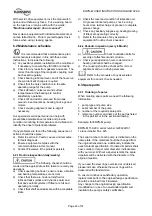
7.3.4 Flushing plan no. 31S according to API 685 


Flushing of magnetic coupling is performed according 
to API 685 flushing plan no.31S. Thereby the pumped 
medium is led to magnetic coupling (connection „F“) 
from pump discharge through a cyclone separator. 
The cyclone separator separates the solids content 
from the pumped medium and returns them to 
suction. 
Clean flushing medium circulates through magnetic 
coupling and enters afterwards into pump casing, into 
the space behind impeller, (low pressure). 
Circulation is necessary for lubricating the bearings 
and for eliminating heat caused by the eddy current 
losses 
 

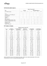
7.3.5 Flushing plan no. 31SE according to API 685 


Flushing of magnetic coupling is performed according 
to API 685 flushing plan no.31SE. Thereby the 
pumped medium is led to magnetic coupling 
(connection „F“) from pump discharge through a 
cyclone separator and a magnetic separator. The 
cyclone separator separates the solids content from 
pumped medium and returns them to suction. The 
cleaned flushing medium runs afterwards through the 
magnetic separator, which separates even the 
smallest metallic parts from the medium. Cleaning of 
magnetic separator should be done regularly 
independently from contamination of medium. 
Clean flushing medium circulates through magnetic 
coupling and enters afterwards into pump casing, into 
the space behind impeller, (low pressure). 
Circulation is necessary for lubricating the bearings 
and for eliminating heat caused by the eddy current 
losses. 


Summary of Contents for ERPN-M

Page 1: ...PN M centrifugal pumps Horizontal End Suction Magnetic Driven PCN 71569270 71569272 71569273 02 08 E Original Instructions Installation Operation Maintenance ПромХимТех официальный дистрибьютор Flowserve www promhimtech ru ...

Page 2: ...ERPN M USER INSTRUCTIONS ENGLISH 02 08 Type ERPN M Size Serial No G208xxx Customer Customer Order No Equipment Item No Pumped Liquid Capacity m h Minimum Capacity m h Head mFs Speed U min 1 ...

Page 3: ...L SHAFT ALIGNMENT CHECK 16 5 0 COMMISSIONING START UP OPERATION AND SHUTDOWN 16 5 1 PRECOMMISSIONING PROCEDURE 17 5 2 PUMP LUBRICANTS 17 5 3 IMPELLER CLEARANCE 22 5 4 DIRECTION OF ROTATION 22 5 5 GUARDING 22 5 6 PRIMING AND AUXILIARY SUPPLIES 22 5 7 STARTING THE PUMP 22 5 8 OPERATION 22 5 9 STOPPING AND SHUTDOWN 22 5 10 HYDRAULIC MECHANICAL AND ELECTRICAL DUTY 23 6 0 MAINTENANCE 23 6 1 GENERAL 23 ...

Page 4: ...ructions Where applicable this document incorporates information relevant to these Directives To establish Approvals and if the product itself is CE Marked check the serial number plate and the Certification 1 3 Disclaimer Information in these User Instructions is believed to be reliable In spite of all the efforts of Flowserve Pump Division to provide sound and all necessary information the conte...

Page 5: ... and training All personnel involved in the operation installation inspection and maintenance of the unit must be qualified to carry out the work involved If the personnel in question do not already possess the necessary knowledge and skill appropriate training and instruction must be provided If required the operator may commission the manufacturer supplier to provide applicable training Always c...

Page 6: ...above 25 kg 55 lbs use a crane corresponding to the mass and in accordance with current local regulations NEVER DO MAINTENANCE WORK WHILST THE UNIT IS CONNECTED TO POWER HAZARDOUS LIQUIDS When the pump is handling hazardous liquids care must be taken to avoid exposure to the liquid by appropriate sitting of the pump limiting personnel access and by operator training If the liquid is flammable and ...

Page 7: ...ry 2 only IIA Propane Typical IIB Ethylene Typical IIC Hydrogen Typical Maximum surface temperature Temperature Class see section 1 6 4 3 1 6 4 3 Avoiding excessive surface temperatures ENSURE THE EQUIPMENT TEMPERATURE CLASS IS SUITABLE FOR THE HAZARD ZONE Pumps have a temperature class as stated in the ATEX Ex rating on the nameplate These are based on a maximum ambient of 40 C 104 F refer to Flo...

Page 8: ... is damp The coupling must be selected to comply with 94 9 EC and correct alignment must be maintained 1 6 4 7 Preventing leakage The pump must only be used to handle liquids for which it has been approved to have the correct corrosion resistance Avoid entrapment of liquid in the pump and associated piping due to closing of suction and discharge valves which could cause dangerous excessive pressur...

Page 9: ...vibration noise level and surface temperature at the bearings to confirm satisfactory operation f Check dirt and dust is removed from areas around close clearances bearing housings and motors g Check coupling alignment and re align if necessary 1 7 Warning label ...

Page 10: ... exceed 85 dBA In such situations consideration must be given to the fitting of an acoustic enclosure Pump noise level is dependent on a number of factors the type of motor fitted the operating capacity pipework design and acoustic characteristics of the building The levels specified in the table below are based on measurements according to EN ISO 3744 for pumps only and not guaranteed The dBA val...

Page 11: ...iameter with water dB correction for combining noises pump motor Difference between two levels to be combined dB Add to the higher level to obtain the combined noise level dB Note 1 The values showed are measured at a distance of 1 mt horizontally from major pump surfaces and 1 5 mt above the floor 2 The values shown are expressed in dB 3 For Noise Test Procedure refer to Works Standard L 109 0 4 ...

Page 12: ...te boxes wrappings for any accessories or spare parts which may be packed separately with the equipment or attached to side walls of the box or equipment Each product has a unique serial number Check that this number corresponds with that advised and always quote this number in correspondence as well as when ordering spare parts or further accessories 2 2 Handling Boxes crates pallets or cartons m...

Page 13: ...ve equipment is used The safety specifications must be in accordance with the current regulations at all times 3 0 DESCRIPTION 3 1 Configuration The model ERPN M belongs to Flowserves family of API 685 magnetic driven end suction pumps The pump line is based on a modular system thus providing maximum design and operating flexibility The pump is available with several impeller designs closed impell...

Page 14: ...ed and prealigned with the motor Also the shaft seal is in the correct position Final alignment after complete installation is necessary If drivers and or seal systems are delivered separately follow the assembly procedure in section 6 8 4 3 Foundation The foundation shall be located on a place that allows a minimum of pipe work and that is easily accessible for inspection during operation Accordi...

Page 15: ... 0 002 in and the axially offset can be 1 mm 0 04 in For more details refer to the manufacturer s instruction manual of coupling a b c a Angular Offset The median lines of shafts intersect half way between the ends of the two shafts a Parallel Offset The median lines run parallel The maximum allowable parallel offset depends on the size of coupling and is indicated in the instruction manual of man...

Page 16: ...ils of the drain connection By pumping toxic or explosive media provide the necessary security actions e g flushing with nitrogen 4 6 Electrical connections Electrical connections must be made by a qualified Electrician in accordance with the relevant local national and international regulations It is important to be aware of the EUROPEAN DIRECTIVE on hazardous areas where compliance with IEC60079...

Page 17: ...e oil mist lubrication For preventing that dirt or humidity get into the bearing housing this pump is equipped with a 1 2 NPT connection for air or nitrogen supply Also at standstill the air or nitrogen supply shall be maintained The pressure shall be between 0 01 bar 0 14 psi and 0 02 bar 0 29 psi otherwise you have to consider an oil leckage and as a result a bearing damage The supplied air or n...

Page 18: ...dy removing the adaptor and fill the reservoir Fully reinserting the adaptor reservoir into the body ensures the previously adjusted oil level is maintained The oiler is equipped with an overflow tube to avoid a rise of the oil level This is necessary to maintain a constant level in an oil bath lubrication system where an oil mist is used as primary lubrication The oiler is preadjusted with the di...

Page 19: ...ted temperature of the bearing housing during a stop of the pump For recommended lubricating oils refer to the lubrication table Having selected the corresponding oil quality the actual oil temperature at the bearing housing must be checked after two service hours of the pump Considering this measured oil temperature the actual viscosity must be determined by using the data sheet of the oil to ver...

Page 20: ...uantity Frame III Bearing size is shown on the name plate of the pump and with this the correct thrust bearing frame can be selected according to the following table Bearing housing 470 with Oiler 357 without Oiler 357 Oil quantity 0 82 l 27 7 Fl oz 0 7 l 23 7 Fl oz 5 2 9 Oil quantity Frame IV Bearing size is shown on the name plate of the pump and with this the correct thrust bearing frame can be...

Page 21: ...P 100 100 1 Alpha SP 220 Alphasyn T 150 synthetic 220 1 150 1 OMV OMV turb HTU 46 46 1 OMV turb HTU 100 100 1 OMV turb HTU 460 460 1 Aral Aral Degol BG 46 Aral Vitam GF 46 46 1 46 1 Aral Degol BG 100 100 1 For temperatures below 5 C 23 F use lubrication oil class SAE 5W 50 or API SJ Seal System Pumped Liquid Quench Oil General Features Barrier Buffer Fluid for Mech Seal Tandem Seal to 40 C 40 F Ba...

Page 22: ...ommended Check the discharge and suction pressure gauge to verify the pumps delivered head The pump must operate smoothly and the vibration must be below 3 mm s 0 2 in sec API 610 vibration limits If a minimum flow valve is installed take pressure gauge readings to verify the correct operation c Check the pipe system against any leakage d Check the magnetic coupling against any leakage Check tempe...

Page 23: ...ould be as large as possible If any change in NPSHA is proposed ensure these margins are not significantly eroded Refer to the pump performance curve to determine exact requirements particularly if flow has changed If in doubt please consult your nearest Flowserve office for advise and details of the minimum allowable margin for your application 5 10 5 Pumped flow Flow must not fall outside the mi...

Page 24: ...ck that there are no abnormal fluid or lubricant leaks static and dynamic seals and that any sealant systems if fitted are full and operating normally c Check that shaft seal leaks are within acceptable limits d Check the level and condition of lubrication oil On grease lubricated pumps check running hours since last recharge of grease or complete grease change e Check any auxiliary supplies eg he...

Page 25: ...LISH 02 08 Page 25 of 37 6 3 2 Storage of spares Spares should be stored in a clean dry area away from vibration Inspection and retreatment of metallic surfaces if necessary with preservative is recommended at a 6 monthly interval ...

Page 26: ... 2 3 6 8 5 M 8 16 2 12 19 8 14 6 23 1 17 7 6 5 6 16 2 12 M 10 31 9 23 6 39 28 8 45 4 33 5 14 9 11 31 9 23 6 M 12 55 4 40 9 67 8 50 78 8 58 2 25 9 19 1 55 4 40 9 M 14 87 9 64 9 107 5 79 3 125 1 92 3 41 30 3 87 9 64 9 M 16 134 6 99 3 164 5 121 4 191 4 141 3 62 8 46 4 134 6 99 3 M 18 188 139 230 170 267 197 88 65 188 139 M 20 263 194 321 237 373 276 123 90 263 194 M 22 353 260 431 318 502 370 165 121...

Page 27: ... seal unit from barrel 471 and pull it of the driving shaft 415 4 Now disassemble carefully seal end plate 506 inclusive gasket 495 cylindrical pin 524 and stationary seal ring G01 together with stationary seal ring packing G03 and throttle ring G02 from barrel 471 5 Furthermore pull off shaft sleeve 509 with O ring 450 and whole rotating unit of mechanical seal G04 G05 G06 G07 from driving shaft ...

Page 28: ...back vanes which shall be checked against any wear 2 Check all parts against corrosion and erosion 3 Carefully check the coupling against any wear 4 Rotate the angular contact bearing by hand to check against abnormal sound Check the bearing cages against any wear and the outer and inner race against running marks Check the runout of the shafts TIR Total Indicated Runout shall not exceed 0 04 mm m...

Page 29: ...into the corresponding hub 3 Now fix radial bearing M04 on casing cover 370 by socket screws 041 so that longitudinal groove of inner diameter lies approximately in horizontal line vertically to resulting radial forces Arrangement of screws allow that the bearing can only be mounted in this position 4 Put shaft sleeve M07 on impeller shaft 417 Alignment of the axial bearing M05 happens simultaneou...

Page 30: ...k whether you can turn rotor by hand Fit the Constant Level oiler and fill oil into bearing housing For correct oil level and adjustment refer to section 5 2 1 Lubrication Frame Thrust bearing Line bearing 1 6306 C3 NU 207 2 6306 C3 NU 207 3 6309 C3 NU 209 4 6309 C3 NU 209 7 0 AUXILIARIES 7 1 Secondary Seal The pump is equipped with a secondary containment seal This can be a non contacting lip sea...

Page 31: ...ushing medium circulates through magnetic coupling and enters afterwards into pump casing into the space behind impeller low pressure Circulation is necessary for lubricating the bearings and for eliminating heat caused by the eddy current losses 7 3 5 Flushing plan no 31SE according to API 685 Flushing of magnetic coupling is performed according to API 685 flushing plan no 31SE Thereby the pumped...

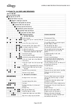
Page 32: ... cut out system design z z z Total head of system higher than differential head of pump Check discharge head and head losses in discharge pipe at the valve settings Check back pressure is not too high z Total head of system lower than pump design head Throttle at discharge valve or ask Flowserve if the impeller can be trimmed z Specific gravity of liquid different from design Consult Flowserve z z...

Page 33: ...llation of bearings Check method of assembly possible damage or state of cleanliness during assembly and type of bearing used z z Damaged bearings due to contamination Check contamination source and replace damaged bearings C ELECTRICAL TROUBLES z z z z Wrong direction of rotation Reverse 2 phases on motor terminal box z z z Motor running too slow Check motor terminal box connections 9 0 CERTIFICA...

Page 34: ... Pumps a reference guide Europump Guide No 1 Europump World Pumps Elsevier Science United Kingdom 1999 Reference 2 Pump Handbook 2nd edition Igor J Karassik et al McGraw Hill Inc New York 1993 Reference 3 ANSI HI 1 1 1 5 Centrifugal Pumps Nomenclature Definitions Application and Operation Reference 4 ANSI B31 3 Process Piping ...

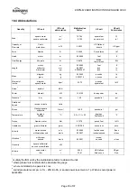
Page 35: ...lowatt kW 1 34102 horsepower hp Pressure 2 bar bar 14 5 pounds in psi Rotational Speed revs per minute r min Stress Newton square millimetre N mm 145 0 pounds in psi Temperature degrees Celsius C 1 8 x C 32 degrees Fahrenheit F Torque Newton meter Nm 0 7376 pound feet lbf ft Unbalance gram millimeter g mm 0 001389 ounce inch oz in Velocity meter second millimeter second m s mm s 3 28084 0 03937 fe...

Page 36: ...FIELD SERVICE REPAIRS EXT 205 SECRETARY EXT 232 EXPORT INVOICING EXT 238 MESSAGES CAN BE LEFT ALSO ON OUR ANSWERING MACHINE IMPORTANT NOTES PLEASE NOTE THAT WARRANTY EXPIRES USE OF NON GENUINE FLOWSERVE AUSTRIA PARTS FOR MAINTENANCE AND REPAIRS NO USE OF OUR SERVICE PERSONAL IN CASE OF REPAIRS DURING WARRANTY PERIOD RECOMMENDATION STARTUP AND COMMISSION SERVICE DIAL EXT 205 PLEASE ASK FOR OUR SPEC...

Page 37: ...oration 5215 North O Connor Blvd Suite 2300 Irving Texas 75039 5421 USA Telephone 1 972 443 6500 Fax 1 972 443 6800 Europe Middle East Africa Worthing S P A Flowserve Corporation Via Rossini 90 92 20033 Desio Milan Italy Telephone 39 0362 6121 Fax 39 0362 303396 Latin America and Caribbean Flowserve Corporation 6840 Wynnwood Lane Houston Texas 77008 USA Telephone 1 713 803 4434 Fax 1 713 803 4497 ...

Reviews: