FRBH, FRBHX AND FRBHS USER INSTRUCTIONS ENGLISH 71569178 20-08
Page 25 of 60
Flowserve.com
®
in the horizontal plane to the motor, There should be
at least 1/16 clearance around the bolt. The coupling
has been designed to have some overhang of the
coupling hub (in most cases 1 or both hubs may be
overhung between 0.0 and 3 mm (0 and 0.12 in)
unless otherwise stated. This procedure ensures that
there is sufficient clearance in the motor holes for the
customer to field align the motor to the pump, to zero
tolerance. This philosophy requires that the customer
be able to place the base in the same condition as
the factory. Thus the factory alignment will be done
with the base sitting in an unrestrained condition on a
flat and level surface. This standard also emphasizes
the need to ensure the shaft spacing is adequate to
accept the specified coupling spacer.
The factory alignment procedure is summarized
below:
a) The baseplate is placed on a flat and level
workbench in a free and unstressed position.
b) The baseplate is leveled as necessary. Leveling
is accomplished by placing shims under the rails
of the base at the appropriate anchor bolt hole
locations. Levelness is checked in both the
longitudinal and lateral directions.
c) The pump is put onto the baseplate, aligned and
leveled. The rear foot piece under the bearing
housing is adjustment as necessary by adding or
removing shims [3126.1] between the foot piece
and the bearing housing or at the baseplate.
d) The motor and appropriate motor mounting
hardware is placed on the baseplate and the
motor is checked for any planar soft-foot
condition. If any is present it is eliminated by
shimming.
e) The motor is fastened in place by tightening two
diagonal motor mounting bolts.
f) The spacer coupling gap is verified. As indicated
the gap may be adjusted to ensure adequate
axial bolt clearance.
g) The parallel and angular vertical alignment is
made by shimming under the motor.
h) The pump and motor shafts are then aligned
horizontally, both parallel and angular, by moving
the pump to the fixed motor. The pump feet are
tightened down.
i) Both horizontal and vertical alignment is again
final checked as is the coupling spacer gap.
See section 4.8,
Final shaft alignment
.
4.5.1
Thermal expansion
The pump and motor will normally
have to be aligned at ambient temperature and
should be corrected to allow for thermal expansion at
operating temperature. In pump installations
involving high liquid temperatures, the unit should be
run at the actual operating temperature, shut down
and the alignment checked immediately.
4.5.2
Alignment methods
Ensure pump and driver are isolated
electrically and the half couplings are disconnected
.
The alignment MUST be checked.
Although the pump will have been aligned at the
factory it is most likely that this alignment will have
been disturbed during transportation or handling. If
necessary, align the motor to the pump, not the pump
to the motor.
4.5.2.1
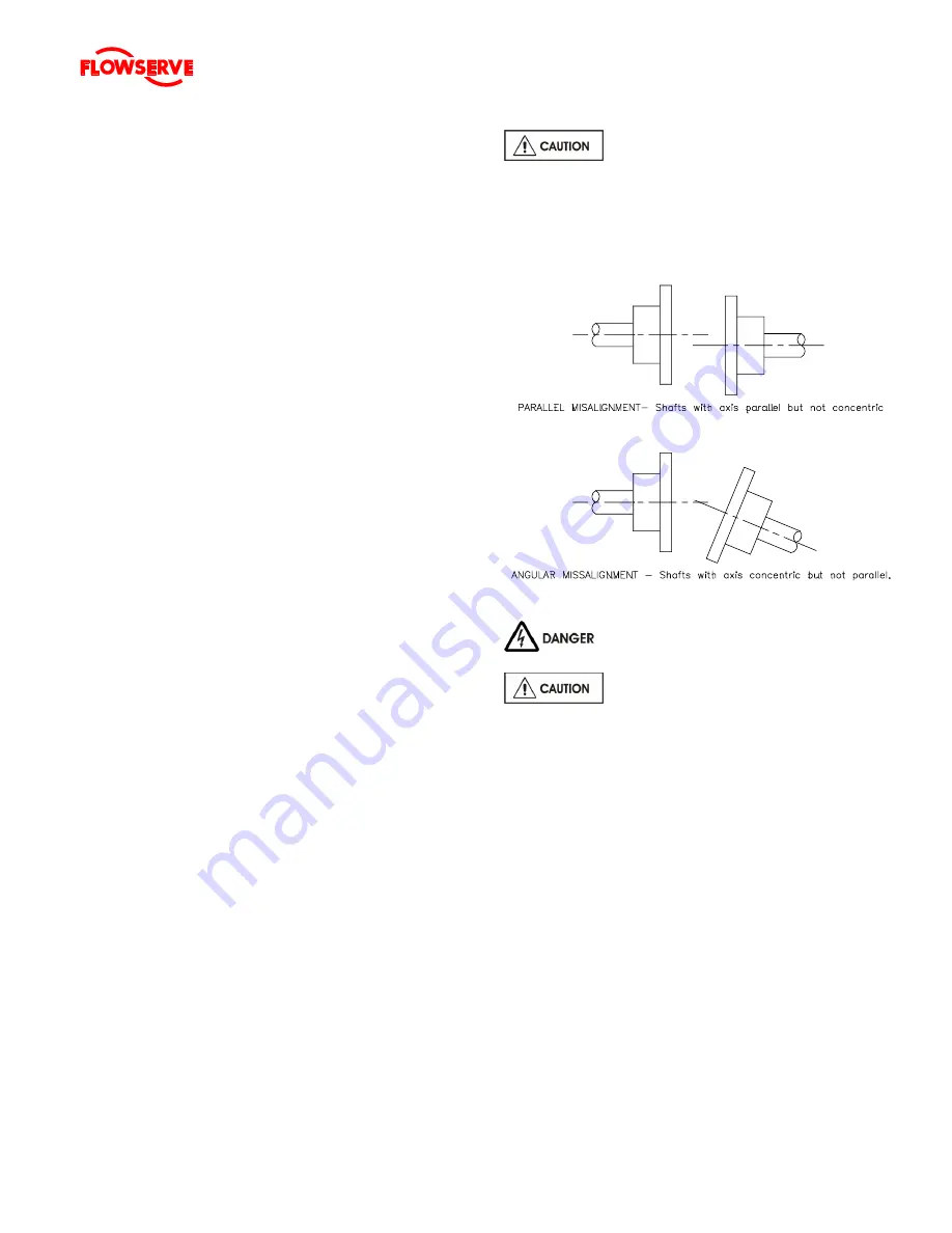
Direct Driven Units:
The importance of accurate alignment of pump
and driver shafts cannot be overemphasized.
IMPROPER ALIGNMENT IS THE PRIMARY
CAUSE OF VIBRATION PROBLEMS AND
REDUCED BEARING LIFE.
A flexible coupling is used to compensate for slight
changes in alignment that occur during normal
operation and is not used to correct for installation
errors. Install the pump and driver half couplings in
accordance with the coupling manufacturer's
instructions. Note that the coupling hub faces are not
always mounted flush with the ends of the shafts.
Place the driver on the baseplate such that the
correct spacing is obtained between the two half
couplings. In the case of electric motors, such as
those with sleeve bearings, it may be necessary to

