FRBH, FRBHX AND FRBHS USER INSTRUCTIONS ENGLISH 71569178 20-08
Page 31 of 60
Flowserve.com
®
4.7.3
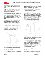
Suction piping
a) The inlet pipe should be one or two sizes larger
than the pump inlet bore and pipe bends should
be as large a radius as possible.
b) Pipework reducers should have a maximum total
angle of divergence of 15 degrees.
c)
On suction lift the piping should be inclined up
towards the pump inlet with eccentric reducers
incorporated to prevent air locks.
d)
On positive suction, the inlet piping must have a
constant fall towards the pump.
e) Flow should enter the pump suction with uniform
flow, to minimize noise and wear. This is
particularly important on large or high-speed
pumps that should have a minimum of four
diameters of straight pipe on the pump suction
between the elbow and inlet flange. See section
10.3,
Reference 1
for more detail.
f)
Inlet strainers, when used, should have a net
`free area' of at least three times the inlet pipe
area.
g) Do not install elbows at an angle other than
perpendicular to the shaft axis. Elbows parallel
to the shaft axis will cause uneven flow.
h)
Except in unusual circumstances strainers are
not recommended in inlet piping. If considerable
foreign matter is expected a screen installed at
the entrance to the wet well is preferable.
i)
Fitting an isolation valve will allow easier
maintenance.
j)
Never throttle pump on suction side and never
place a valve directly on the pump inlet nozzle.
4.7.4
Discharge piping
A non
-
return valve should be located in the
discharge pipework to protect the pump from
excessive back pressure and hence reverse rotation
when the unit is stopped.
Pipework reducers should have a maximum total
angle of divergence of 15 degrees.
Fitting an
isolation valve will allow easier maintenance.
4.7.5
Auxiliary piping
4.7.5.1
Drains
Pipe pump casing drains and gland leakage to a
convenient disposal point.
4.7.5.2
Pumps fitted with gland packing
When suction pressure is below ambient pressure it
is necessary to feed the gland packing with liquid to
provide lubrication and prevent the ingress of air.
This is normally achieved with a supply from the
pump discharge volute to the stuffing box. A control
valve is fitted in the line to enable the pressure to the
gland to be controlled.
If the pumped liquid is dirty and cannot be used for
sealing, a separate clean compatible liquid supply to
the gland at 1 bar (15 psi) above suction pressure is
recommended.
4.7.5.3
Pumps fitted with mechanical seals
Single seals requiring re
-
circulation will normally be
provided with the auxiliary piping from pump casing
already fitted.
If the seal requires an auxiliary quench then a
connection must be made to a suitable source of
liquid flow, low pressure steam or static pressure
from a header tank. Recommended pressure is 0.35
bar (5 psi) or less. Check
General arrangement
drawing
.
Special seals may require different auxiliary piping to
that described above. Consult separate User
Instructions and/or Flowserve if unsure of correct
method or arrangement.
For pumping hot liquids, to avoid seal damage, it is
recommended that any external flush/cooling supply
be continued after stopping the pump.
4.7.6
Final checks
Check the tightness of all bolts in the suction and
discharge pipework. Check also the tightness of all
foundation bolts.
4.8
Final shaft alignment check
After connecting piping to the pump, rotate the shaft
several times by hand to ensure there is no binding
and all parts are free.
The baseplate should be levelled and grouted by this
stage.
Recheck the coupling alignment, as previously
described, to ensure no pipe strain. If pipe strain
exists, correct piping.
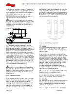
a) Mount and level pump if appropriate. Level the
pump by putting a level on the discharge flange.
It may be necessary to adjust the bearing frame
foot by adding or deleting shims [3126.1]
between the foot piece and the bearing housing
(or baseplate).
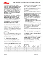
b) Check initial alignment. If pump and driver have
been remounted or the specifications given
below are not met, perform an initial alignment
as described in section 4.5. This ensures there
will be sufficient clearance between the motor
hold down bolts and motor foot holes to move

