FRBH, FRBHX AND FRBHS USER INSTRUCTIONS ENGLISH 71569178 20-08
Page 45 of 60
Flowserve.com
®
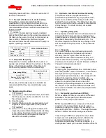
c) Install the remaining capscrews and lockwashers.
Assemble the jam nuts on the jacking screws and
assemble these into the thrust bearing housing
[3230].
d) Carefully install the lip seal [4300] in the bearing
cover [3260] by pressing it squarely into the bore.
The primary sealing lip [spring loaded] on seal
should be installed facing the bearing. A small
amount of sealant may be applied on the O.D. of the
seal prior to it's installation.
e) Lubricate the o-ring [4610.3] and assemble into the
groove of the line bearing cover.
f) Assemble the line bearing cover [3260] over the
shaft and squarely into the bearing frame bore.
Fasten to the bearing frame with capscrews,
washers and hex nuts. Tighten firmly, but not
excessively.
g) Assemble the deflector [2540] loosely over the shaft
but do not tighten the set screws.
h) Install the coupling key [6700] and tape to the shaft.
i) Mount a dial indicator to the bearing frame [3130]
and indicate shaft under bearing frame flange
(approx. mid way between impeller mounting face
and end of sleeve area. Rotate shaft and check that
runout does not exceed 0.002 inch (0.050 mm).
6.10.5
Stuffing box
6.10.5.1
All
a) Install the gland studs [6573] using Loctite grade A
or equivalent. Install the square head plugs [211 in
the stuffing box as required using pipe sealant.
b) The gland studs [6573] on water cooled stuffing
boxes must be sealed with pipe sealant. If only two
gland studs are used, the remaining two tapped
holes must be plugged with set screws or short
capscrews. To ensure proper sealing, the chamber
can be tested to a design pressure of 75psi.
c) Press the stuffing box neck bush [4132] into the
stuffing box [4100], ensuring that it seats squarely on
the shoulder.
d) Lubricate the pump shaft [2110] at the impeller
position, check the fit of the impeller key [6700] in the
shaft keyway and. Install the impeller [2200] onto the
shaft to ensure that there is a good sliding fit.
Remove the impeller [2200] and the impeller key
[6700].
e) Install the o-ring [4610] into the impeller nut [2912]
using grease or anti-seize compound to hold it in
place during assembly.
f)
Install the shaft sleeve [2445] onto the shaft [2110]
and orientate the sleeve such that the keyways are
aligned. Install the impeller key [6700] in the shaft.
6.10.5.2
Standard packing
a) Assemble the stuffing box head [4100] over the shaft
sleeve [2445] and orientate the lantern ring
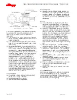
connections to auxiliary piping (Refer to Figure 6).
These connections are normally placed on the
vertical centerline for proper venting and draining as
well as providing optimum gland stud access.
b) Push the stuffing box head [4100] back against the
bearing frame flange face. Back off the thrust
bearing housing jacket screws and tighten the thrust
bearing hold down screws to slide the rotor assembly
forward such that the end face of the shaft sleeve
[2445] protrudes beyond the box face.
c) Install the shaft gasket [4590.2] onto the shaft,
ensuring that the outside diameter is no larger than
the sleeve.
6.10.5.3
Optional expeller seal-frame 1, 2 & 3
a) Assemble the stuffing box [4100] over the shaft
sleeve [2445] and into the bearing bracket [3130]
register. Orient the grease fitting to suit the
installation. Note that if the optional solid gland with
lip seal design is used, it must be installed first.
b) Assemble the o-ring [4610.2] into the groove of the
stuffing box [4100].
c) Adjust the pump shaft [2110] forward to ensure that
the Radial impeller [2250] when installed will not bind
against the stuffing box head [4100].
d) Assemble the gasket [4590] on to the shaft against
the shaft sleeve [2445]. A small amount of grease
may be used to hold the gasket while other parts are
assembled.
e) Install the expeller [2250] onto the shaft sleeve
[2445] vales first.
6.10.5.4
Optional expeller seal-frame 4
a) Assemble the stuffing box [4100] over the shaft
sleeve [2445] and into the bearing bracket [3130]
register. Orient the grease fitting to suit the
installation. Note that if the optional solid gland with
lip seal design is used, it must be installed first.
b) Assemble the o-ring [4610.2] into the groove of the
stuffing box [4100].
c) Adjust the pump shaft [2110] forward to ensure that
the radial impeller [2250] when installed will not bind
against the stuffing box head [4100].
d) Assemble the o-ring [4610.5] in the bore of the radial
impeller [2250].
e) Install the drive impeller key [6700] on the pump
shaft [2110].
f) Install the radial impeller [2250] onto the shaft sleeve
[2445] vanes first.
g) Install the o-ring [4610.5] in the groove of the
expeller hub face.
6.10.6
Impeller Installation
a) Adjust the rotor assembly such that the radial
impeller [2250] is recessed within the stuffing box
cavity. Assemble the expeller housing [4110] onto
the stuffing box [4100].
b) Install impeller [2200].
c) Apply a small quantity of Loctite 242 or equivalent to
the exposed thread on the end of the shaft, and
thread the impeller nut [2912] complete with o-ring
[4610] onto the shaft.

