FRBH, FRBHX AND FRBHS USER INSTRUCTIONS ENGLISH 71569178 20-08
Page 46 of 60
Flowserve.com
®
For units with mechanical seals, do not
apply thread locking compound until seal axial
setting has been established.
d) Tighten the impeller nut [2912] in accordance with
Table 6.6. This is an essential step to properly seat
the shaft sleeve [2445] and compress the gasket
[4590.2] to provide a seal and to prevent loosening
of the impeller on the shaft.
e) Release the thrust bearing housing hold down bolts
and tighten the jacking screws to pull the impeller
back to the stuffing box head [4100]. The stuffing
box head must not be rigidly clamped.
6.10.7
Wearplate
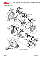
a) Install the studs [6572] in the wearplate [1915] using
Loctite grade A or equivalent. Place the sealing
washer [4590.1] over the studs [6572] and install the
wearplate into the pump casing [1110]. Secure
wearplate [1915] in place using hex nuts and
washers using Loctite 242 or equivalent. Tighten in
accordance with Table tables in section 6.6.
Excessive or uneven tightening torque may distort wearplate
affecting impeller running clearances or result in broken
studs.
b) Stand the casing on it's feet.
c) Smear a small amount of grease or anti-seize
compound over one face of the gasket [4590.3] and
place it on the stuffing box head [4100] with coated
face against flange.
Some sizes, as identified in Section I use an o-
ring in place of a gasket.
6.10.8 FRBHS only
a) Take spacer and install gasket [4590.3] with a small
amount of grease on the face that will mate inside
the pump casing [1110].
b) Smear anti-seize compound on the pump casing
[1110] and adapter [1340] rabbit fit (spigot)
diameters to ease assembly and future disassembly.
c) Install the adapter/gasket [1340/4590.3] into the
pump casing [1110].
This piece is loose so caution must be
exercised when moving around the casing.
6.10.9
All pumps except FRBHS
a)
Smear anti-seize compound on the pump casing
[1110] and stuffing box head [4100] rabbit fit (spigot)
diameters to ease assembly and future disassembly.
6.10.10
Rotor unit
a) With a sling around the bearing frame placed so as
to balance the weight, lift the frame/impeller
assembly keeping the shaft horizontal.
b) Install the frame/impeller assembly into the pump
casing [1110] by guiding the stuffing box head and
bearing frame spigots squarely into the casing
recess. Ensure that the gasket [4590.3] stays in
position. If the fit becomes snug, use 4 equally
spaced bolts to draw the assembly into the casing.
c) Install the casing frame bolts with washers and
tighten in accordance with Table 6.6.
d) Using the thrust bearing housing adjustment feature
[Figure 8], move the impeller forward away from the
stuffing box head [4100].
e) Attach the bearing frame support foot [3134] to the
bearing bracket [3130] using the capscrews and
washers. Ensure that thread engagement is atleast 1
diameter. Use Loctite 242 thread sealant.
lockwashers should not be used to ensure
proper thread engagement with standard bolting.
f) Set the impeller front clearance in accordance with
instruction earlier in this section of the manual.
6.10.11
Shaft seal
6.10.11.1
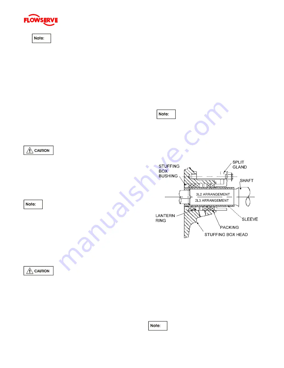
Packing
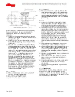
Standard Packed Box Arrangement
a)
Insert one packing ring at a time into the stuffing box.
Push the packing as far as possible into the packing
bore.
b)
Install additional rings as required, staggering the
joints.
c)
Once the first two or three rings of packing have
been inserted, the two piece lantern ring [4134] must
be installed. Push the lantern ring and previously
installed packing. The ports in the lantern ring do not
need to be aligned with the inlet/outlet ports.
d)
Ensure that the shaft can be turned by hand.
e)
Install the remaining rings of packing, alternating the
joints.
It may not be possible to insert the last ring in

