FRBH, FRBHX AND FRBHS USER INSTRUCTIONS ENGLISH 71569178 20-08
Page 24 of 60
Flowserve.com
®
4.4.2.3 Fill the baseplate with grout noting that the
weight of grout has been estimated and is shown
on the pump general arrangement. It is
recommended that the mass be /- 2% of
that shown. Generally more mass will not be
detrimental to the design but could mean the
nominal spring compression may be more. The
springs have been designed for a certain amount of
deflection but the springs do have and will require
adjustment. This will be discussed later.
4.4.2.4 Allow the grout to harden. Drying time
required will be specified by the concrete/grout
supplier.
4.4.2.5 If base plate in rough position it will be
necessary to move so that springs can be
mounted. The followings steps to mount the
springs have been provided by the isolator (spring)
manufacturer (VMC) and adapted to Flowserve’s
pumps.
4.4.2.6 Isolators are shipped fully assembled and
are to be placed and arranged in accordance with
the installation (general arrangement) drawing.
4.4.2.7 Set isolators on the floor/foundation or sub-
base, ensuring that all isolator centerlines match
equipment mounting holes.
4.4.2.8 In most cases the isolators will be same
model and size. If multiple sizes of isolators are to
be used the detail and pattern will be shown on the
pump’s general arrangement drawing. Each
isolator should be tagged and labelled. The springs
themselves are color coded for easy identification.
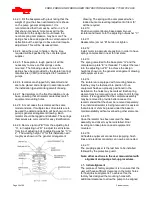
4.4.2.9
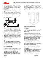
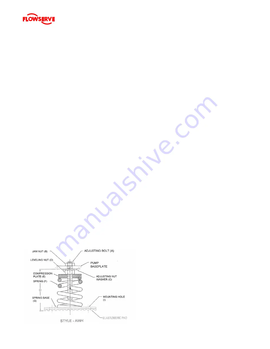
Remove jam nut “B” from the adjusting bolt
“A”, turn adjusting nut “D” to adjust to set distanc
e
from top of adjusting bolt to adjusting washer “C” to
2”. The working height “H” for this installation will
roughly as shown on the general arrangement
drawing. The spring will be compressed when
loaded but some level
ling/adjustment of item “E”
will be required.
4.4.2.10
Position equipment/pump base assembly over
isolators and lower onto the adjusting nut washer “C”.
4.4.2.11
Reassemble jam nut “B” but do not tighten.
4.4.2.12
Install motor in approximate position in order to have
springs compressed in near to final state
4.4.2.13
The spring is welded to the base plate “G” and the
compression plate “E” is threaded. To adjust the level
turn the adjusting nut “D” to achieve the design
height as shown on the general arrangement drawing
and equipment level.
4.4.2.14
The isolators are equipped with mounting holes so
that they may be fastened into position. Once
equipment has been properly positioned in the
installation, the holes may be marked. Each spring
element may be removed one at a time to drill for lag
screws. It is suggested that the complete assembly
may be removed to provide better access. It is
recommended that the driver be removed separately.
If an individual isolator is being removed it is advised
that a block or shim be placed under the base to
maintain stability without overloading other elements.
4.4.2.15
Once the isolator has been secured the base
assembly and driver may be reinstalled. Final
levelling can take place once all equipment is
mounted.
4.4.2.16
All flexible equipment connections (ie piping, flush
lines and electrical conduits) can now be connected.
4.4.2.17
The coupling spacer is the last item to be installed
followed by the protective guard.
Note: other sections in the user manual deal with
alignment and pump start-up procedures.
4.5
Initial alignment
The purpose of factory alignment is to ensure that the
user will have sufficient clearance in the motor holes
for final job-site alignment. To achieve this, the
factory has designed the mounting holes with
additional clearance to allow the pump to be aligned

