FRBH, FRBHX AND FRBHS USER INSTRUCTIONS ENGLISH 71569178 20-08
Page 27 of 60
Flowserve.com
®
on its magnetic centreline. A button (screwed into
one of the shaft ends) is normally fitted between the
motor and pump shaft ends to fix the axial position.
If the motor does not run in its
magnetic centre the resultant additional axial force
may overload the pump thrust bearing.
Complete piping as below and see sections
4.7,
Final shaft alignment check
up to and including
section 5,
Commissioning, startup, operation and
shutdown
before connecting driver and checking
actual rotation.
4.5.5
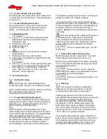
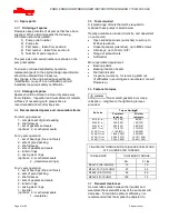
Check for Soft foot
This is a check to ensure that there is no undue
stress on the driver holding down bolts; due to non
-
level baseplate or twisting. To check, remove all
shims and clean surfaces and tighten down driver to
the baseplate. Set a dial indicator as shown in
sketch and loosen off the holding down bolt while
noting any deflection reading on the dial test Indicator
-
a maximum of 0.05 mm (0.002 in.) is considered
acceptable but any more will have to be corrected by
adding shims. For example, if the dial test indicator
shows the foot lifting 0.15 mm (0.006 in.) then this is
the thickness of shim to be placed under that foot.
Tighten down and repeat the same procedure on all
other feet until all are within tolerance.
Complete piping as below and see sections
4.7,
Final shaft alignment check
up to and including
section 5,
Commissioning, start-up, operation and
shutdown
before connecting driver and checking
actual rotation.
4.5.6
V-Belt Drive Units:
Check that both sheaves are free of grease, rust, nicks
or burrs. Install the correct size sheave on the pump
shaft and locate the sheave axially to minimize
overhang. Re-check the impeller axial clearance and
ensure that the pump is properly secured to the
baseplate. Install the driver on the adjustable base
provided and install the driver sheave in line with the
pump sheave. Ensure that the sheaves are tight on the
shafts. With a dial indicator, check the runout on the
periphery and face of each sheave to ensure that each
is running true. Tighten the adjustable base and check
that the driver rotation in the correct direction and that
vibration levels are not unacceptable.
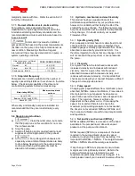
Checking V-Belt Sheave Alignment:
Before starting the driver, refer to the
man
ufacturer’s instruction manual. The correct
rotation of the pump shaft is marked on the pump
casing or frame.
Check that all belts making up one drive set have
matched code numbers. Loosen the adjustable base
and install the belts in their proper grooves. Adjust
the center distance between the sheaves to obtain
proper belt tension. Check the alignment of the pump
and driver sheaves with a taught string or straight
edge. For proper alignment and the sheave faces
must be parallel to each other and in line.
Adjustments are made by slackening the belts,
moving and retightening the drive or driver sheave,
and repeating the above procedure.
When the sheaves are aligned that the shafts rotate
freely by hand and install safety guard.
Belt drives must not be used in ATEX Potentially
explosive environments; refer to Flowserve.
4.6
Grouting
The purpose of grouting is to provide rigid support to
the pump and driver by increasing the structural
rigidity of the baseplate and making it an integral
mass with the foundation.
Clean the roughed foundation surface and build a


