HDX USER INSTRUCTIONS ENGLISH 85392696 - 01/11
Page 37 of 60
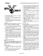
i) It is advisable to thoroughly drain and dry off the
base plate before attempting any maintenance
work on the pump.
This could eliminate the risk of slipping on a
wet surface causing personal injury or mechanical
damage.
j) Remove pump monitoring equipment, auxiliary
services or any other plant or equipment that may
interfere with safe dismantling of the pump.
k) Loosen set screw securing coupling nut and
remove nut.
l) Remove pump coupling hub, using a puller.
Remove coupling key.
m) When cartridge type mechanical seals are used,
loosen seal drive collar set screws. Insert first
locking tab into seal sleeve groove. Consult
mechanical seal manufacturer’s instructions.
n) Proceed now with the dismantling of the pump
following the steps listed below. For location of
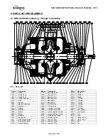
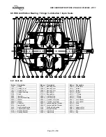
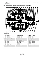
parts refer to pump sectional drawing and part
list.
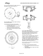
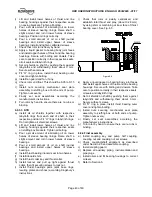
6.7.2 Thrust Bearing Disassembly
6.7.2.1 Ball Ball
a) Remove outer bearing cover.
b) Release locking tab of thrust bearing lock-
washer.
c) Loosen and remove bearing lock nut and lock-
washer.
d) Remove spacer together with slinger.
e) Unbolt screws fixing the inner cover.
f) Pull out thrust bearing housing.
g) Fit a bearing puller on the inner shield and pull
out thrust bearing assembly together with inner
bearing cover and shield.
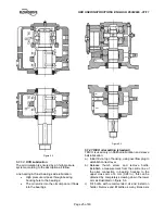
6.7.2.2 Sleeve Ball
a) Remove fan guard and fan, if any.
b) Remove bolting securing end cover to bearing
housing and remove cover.
c) Remove all bolting and taper pins holding upper
half of thrust bearing housing and remove it. Use
jack bolts and eyebolts for removal.
d) Unbolt calibrated screws and remove top half
sleeve bearing.
e) Slide oil rings onto shaft apart from lower half
sleeve bearing.
f) Carefully lift pump shaft just enough so that lower
half sleeve bearing can be removed.
g) Unbolt and remove lower half of thrust bearing
housing.
h) Release locking tab of thrust bearing lock-
washer. Loosen and remove thrust bearing lock
nut and lock-washer.
i) Remove thrust bearing assembly, using a puller
that will bring pressure against inner bearing race
only.
j) Remove oil rings. Unscrew set screws and
remove inboard oil shield together with labyrinth
ring.
6.7.2.3 KTB
a) Remove bolting securing end cover to bearing
housing and remove cover along with outboard
shim.
b) Remove all bolting and taper pins holding upper
half of thrust bearing housing and remove it. Use
jack bolts and eyebolts for removal.
c) Remove top half sleeve bearing.
d) Remove thrust shoes, leveling plates and split
base rings. Consult Kingsbury’s instructions.
e) Unscrew set screws and remove thrust collar
locking nut.
f) Remove thrust collar and key. Remove inboard
shim and oil seal in two halves.
g) Carefully lift pump shaft just enough so that lower
half sleeve bearing can be removed.
h) Unbolt and remove lower half of thrust bearing
housing.
i) Remove inboard labyrinth ring. Unscrew set
screws and remove inboard oil shield.
6.7.3
Line Bearing Disassembly
6.7.3.1 Ball Ball
a) Unscrew grub screws and remove outer shield.
b) Unbolt outer bearing cover.
c) Release locking tab of line bearing lock- washer.
d) Loosen and remove bearing lock nut and lock-
washer.
e) Remove spacer together with oil ring.
f) Unbolt inner cover fixing screws.
g) Pull out line bearing housing.
h) Fit a bearing puller on the inner shield and pull
out line bearing, inner bearing cover and shield
contemporary.
6.7.3.2 Sleeve Ball
a) Remove fan guard and fan, if any.
b) Remove all bolting and taper pins holding upper
half of line bearing housing and remove it. Use
jack bolts and eyebolts for removal.
c) Unbolt calibrated screws and remove top half
sleeve bearing.
d) Slide oil rings onto shaft apart from lower half
sleeve bearing

