HPXM USER INSTRUCTIONS ENGLISH 14983571 - 03/11
Page 24 of 48
•
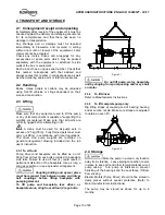
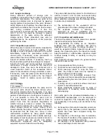
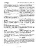
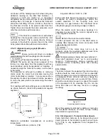
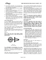
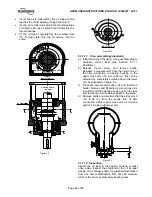
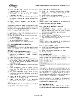
(3)-(4) the oil is collected by the oil collector and
reaches the thrust bearing through the hole “F”
•
(6) the oil is collected behind the thrust bearings
and returns into the oil sump once it flows into the
thrust bearings
•
(7) the oil level is regulated by the overflow hole
“G”. Through this hole the oil returns into the
sump.
A
B
SECTION A − A
1
2
3
E
E
4
5
B
A
F
bearing frame
top view
G
4
Figure 5.2
SECTION B − B
F
4
6
7
G
Figure 5.2
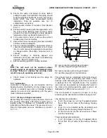
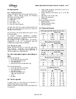
5.1.1.1.1 Trico oiler setting (standard)
a) Initial fill via top of housing, using overflow plug to
establish correct level (see Section 5.1.1.1
illustration).
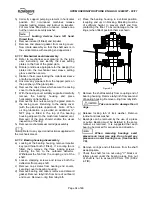
b) Release thumb screw and remove bottle.
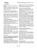
Establish a measurement from the centre line of
the oiler connection in bearing housing to the
upper cross arm of 6 mm (0.24 in.); this can be
obtained by completely screwing down the lower
arm as illustrated on figure 5.3.
c) Fill bottle with recommended oil and install on
holder. Remove and fill bottle as many times as is
required to fill the bearing housing up to the cross
arm level and no air bubbles appear in the bottle.
d) Remove bottle and ascertain that the oil level is 6
mm (0.24 in.) from the centre line of oiler
connection. Adjust upper cross arm as required
and lock in place with lower arm.
Figure 5.3
5.1.1.1.2 Inspection
Inspect the oil level in the bearing housing at least
once a day. Inspect the condition of the oil at least
weekly. Oil is always subject to gradual deterioration
from use and contamination from dirt and moisture
which is the cause of premature bearing wear.

