HPXM USER INSTRUCTIONS ENGLISH 14983571 - 03/11
Page 25 of 48
For oil lubricated pumps, fill the
bearing housing with correct grade of oil to the
correct level, i.e. constant level oiler bottle (standard
configuration) and sight glass (when fitted on
request).
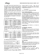
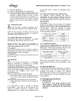
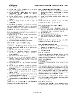
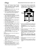
Figure 5.4
Sight glass
5.1.1.1.3 Replenishment
Replenish the oil in the oiler as required. More
frequent replenishment at high temperatures may be
required.
5.1.1.1.4 Oil change
Frequency of oil change is dependent on pump
service and environmental conditions. As a general
guide, oil in the bearing housing should be changed
every 4000 operating hours, after the initial change.
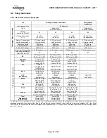
5.1.1.1.5 Lubrication Specification
The ideal bearing lubricant is a straight well refined,
neutral mineral, preferably of the turbine type. It
should not contain free acid, chlorine sulphur or more
than a trace of free alkali. It is suggested that the oil
conform to the following physical characteristics.
5.1.1.2 Pure Oil Mist Lubrication
If the pump bearing housing is arranged for pure oil
mist lubrication the following connections are
provided in the bearing housing:
-
¼” NPT with adapter oil mist inlet connection in
the top half of the bearing housing, between line
and thrust bearings.
-
¼” NPT vent connection in the space between
the rolling element bearing and the
inboard/outboard bearing housing cover.
-
½” NPT drain connection in the bottom half of the
bearing housing.
Remove inlet and outlet pipe plugs from above
connections. Install appropriate reclassifier in the top
opening, leave open vent connections, connect oil
recovery trap to bottom opening or leave it open to
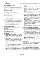
act as a relief. Refer to Figure 5.5 for details.
Figure 5.5
No oil ring, slinger or constant level oiler are supplied.
5.1.1.3 Purge Oil Mist Lubrication
If the pump bearing housing is arranged for purge oil
mist lubrication the following connections are
provided in the bearing housing:
-
¼” NPT with adapter oil mist inlet connection in
the top half of the bearing housing, between line
and thrust bearings.
-
¼” NPT vent connection in the space between
the rolling element bearing and the
inboard/outboard bearing housing cover.
-
½” NPT drain connection in the bottom half of the
bearing housing.
Remove inlet and outlet pipe plugs from above
connections. Install appropriate reclassifier in the top
opening, leave open vent connections, connect oil
recovery trap to bottom opening or leave it open to
act as a relief. Refer to Figure 5.5 for details.
Also this configuration include the internals like
slinger or oil ring as specified in section 5.1.1.1 and a
special constant level oiler designed for the Purge
arrangement.

