HPXM USER INSTRUCTIONS ENGLISH 14983571 - 03/11
Page 32 of 48
6.3 Spare parts
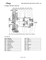
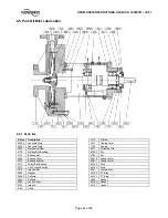
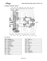
6.3.1 Ordering of spares
Flowserve keep records of all pumps that have been
supplied. When ordering spares the following
information should be quoted:
1) Pump serial number
2) Pump
size
3) Part name – (a)
4) Part number – (a)
5) Number of parts required
(a) taken from the cross section drawing stored into
the job user instruction book and only in case not
available see at section 8.
The pump size and serial number are shown on the
pump nameplate.
To ensure continued satisfactory operation,
replacement parts to the original design specification
should be obtained from Flowserve.
Any change to the original design specification
(modification or use of a non-genuine part) will
invalidate the pump’s safety certification.
6.3.2 Storage of spares
Spares should be stored in a clean dry area away
from vibration. Inspection and re-treatment of
metallic surfaces (if necessary) with preservative is
recommended at 6 monthly intervals.
6.4 Recommended spares (according to
API)
For start up purposes:
1 - set of bearings (line and thrust)
2 - sets of gaskets and o-ring
1 - mechanical seals
1 - labyrinth set (drive and impeller end)
For normal maintenance:
1 - set of bearings (line and thrust)
2 - sets of gaskets and o-ring
1 - mechanical seals
1 - labyrinth and deflector set
(drive and impeller end)
1 - shaft
1 - impeller
6.5 Tools required
A typical range of tools that will be required to
maintain these pumps is listed below.
Readily available in standard tool kits, and dependent
on pump size:
•
Open ended spanners (wrenches) to suit up to
2” (M 50) screws/nuts
•
Socket spanners (wrenches), up to 2” (M 50)
screws
•
Allen keys, up to 10 mm (A/F)
•
Range of screwdrivers
•
Soft
mallet
More specialized equipment:
•
Bearing
pullers
•
Bearing induction heater
•
Dial test indicator
6.6 Fastener torques
Main Flange Studs/Nuts (Casing to Casing Cover)
Torque Value
Stud Size
N
y
m
(lb
y
ft)
¾ in.
⅞
in.
1 in.
1
⅛
in.
225-264
358-420
548-644
870-1024
(166-195)
(264-310)
(404-475)
(642-755)
Bearing Housing to Casing Cover
Torque Value
Hex Head
Screw Size
N
y
m
(lb
y
ft)
½ in.
⅝
in.
18-22
37-45
(13-16)
(27-33)
Bearing Housing End Cover to Bearing Housing
Torque Value
Hex Head
Screw Size
N
y
m
(lb
y
ft)
⅜
in.
8-11
(6-8)
Mechanical Seal to Casing Cover
Torque Value
Stud/Nut Size
N
y
m
(lb
y
ft)
½ in.
⅝
in.
¾ in.
35-41
58-68
130-150
(26-30)
(45-50)
(95-110)
Thrust Bearing Locknut
Torque Value
Bearing Size
N
y
m
(lb
y
ft)
7307
7308
7309
7310
7311
7312
7313
7314
7315
7316
7320
37 – 39
50 – 53
65 – 68
81 – 85
99 – 104
118 – 125
138 – 145
159 – 167
180 – 190
203 – 214
250 – 263
(27 – 29)
(37 – 39)
(48 – 50)
(60 – 63)
(73 – 77)
(87 – 92)
(102 – 107)
(117 – 123)
(133 – 140)
(150 – 158)
(184 – 194)

