HPXM USER INSTRUCTIONS ENGLISH 14983571 - 03/11
Page 33 of 48
Inboard/Outboard Flingers & Oil Thrower
Torque Value
Socket Head
Capscrew Size
N
y
m
(lb
y
ft)
¼ in.
4-5
(3-4)
Torque Values listed above are selected to achieve
the correct amount of pre-stress in the threaded
fastener. Maintenance personnel must ensure that
threads are in good condition (free of burrs, galling,
dirt, etc.) and that commercial thread lubricant is
used. Torque should be periodically checked to
ensure that it is at the recommended value.
6.7 Disassembly
Refer to section 1.6,
Safety
, before dismantling
the pump.
Before dismantling the pump for
overhaul, ensure genuine Flowserve replacement
parts are available.
Refer to sectional drawings for part
numbers and identification.
Before attempting to disassemble the pump,
the pump must be isolated from the system, by
closing suction and discharge system valves,
drained of liquid and cooled, if pump is handling
hot liquid.
Before attempting any maintenance work on
pumps in vacuum service, the pumps must be
isolated from suction and discharge system then
carefully vented to return pressure in pump
casing to atmospheric pressure.
Remove the pipe plug(s) from the
top of the bearing housing(s) and check to see
that oil rings are riding free on the pump shaft
and are not hung up. Failure to observe this
caution could result in damage to or destruction
of equipment.
6.7.1 Disassembly of Pull Out Element
This is a pull from rear design, so it is not necessary
to remove casing, or to detach suction or discharge
piping, coupling hubs or to remove driver.
a) Remove all seal piping, related instrumentation
and electrical equipment that will interfere with
disassembly. Drain pump casing.
When pump is handling "hot" liquid extreme
care must be taken to ensure safety of personnel
when attempting to drain pump. Hot pumps must
be allowed to cool before draining.
When pump is handling "caustic" liquid
extreme care must be taken to ensure safety of
personnel when removing auxiliary piping or
when draining pump. Protective devices of
suitable protective materials must be worn when
draining the pump.
b) Disassemble and remove coupling guard and
coupling spacer.
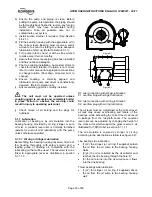
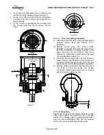
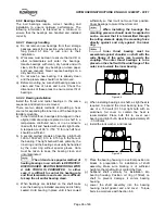
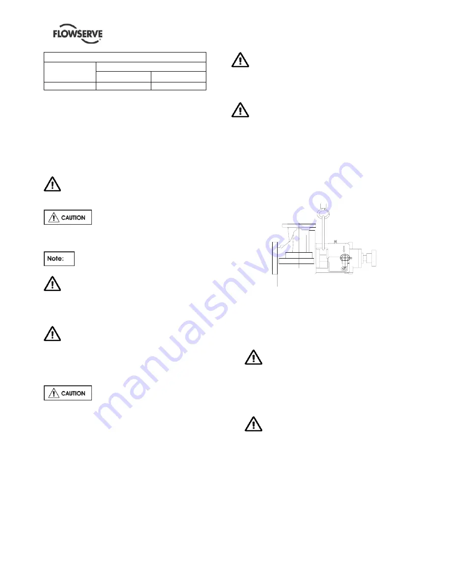
c) Place lifting straps around bearing bracket at seal
area. Take a slight strain on slings.
Figure 6.1
location of lifting straps for removing pumping element
d) Drain the bearing housing of oil. This can be
done by removing the drain plug situated at the
bottom of the bearing housing.
Use caution when draining hot oil from
bearing housing to prevent burns/injury to
personnel
e) It is advisable to thoroughly drain and dry off the
baseplate before attempting any maintenance
work on the pump.
This could eliminate the risk of slipping
on a wet surface causing personal injury or
mechanical damage.
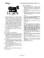
f) Remove casing cover to casing main flange
bolting. Install two jack screws (provided) in
casing cover. Tighten jack screws evenly to
separate joint between casing cover and casing.
g) Carefully withdraw pumping element from casing
until impeller (or inducer when fitted) is clear of
casing. Move pumping element to area where
disassembly will be performed.

