background image

HPXM USER INSTRUCTIONS  ENGLISH  14983571 - 03/11

Page 36 of 48

6.9.2  Bearings Housing

The ball bearings require correct handling and
installation to ensure optimum performance. The
following information is intended as a minimum to
ensure that the bearings are handled and installed
correctly.

6.9.2.1  Bearings handling

a)  Do not remove new bearings from their storage

package except for inspection, when stored for a
long period of time or just prior to their
installation.

b)  Work area must be clean to ensure that no dirt or

other contaminates will enter the bearings.
Handle bearings with clean, dry hands and with
clean, lint free rags. Lay bearings on clean paper
and keep covered.  Never expose bearings on a
dirty bench or floor.

c)  Do not wash a new bearing. It is already clean

and the preservative should not be removed.

d)  Before mounting, be sure shaft bearing areas are

clean and free of nicks and burrs. Check the
dimensions of these areas to ensure correct fit of
bearings.

6.9.2.2  Bearing installation

Install the thrust and radial bearings in the same
sequence and direction as removed.
There are two simple methods of providing a heat
source for expanding the inner race of the bearings to
facilitate mounting.
a)  In the first method, bearings still wrapped in their

original intimate wrap are placed on a shelf in a
temperature controlled oven, or in an enclosure
lined with foil


and heated with electric light bulbs.

A temperature of 66 °C (150 °F) for one half hour
should be sufficient.

b)  A second method consists of locating a light bulb

100 to 150 Watt ( 0.13 to 0.15 hp) in the bore of
the bearing. The light bulb will heat, primarily, the
inner ring and the bearing can usually be handled
by the outer ring without special gloves. Care
must be taken to keep the bearing clean and
uncontaminated.


The old and once popular method of

heating bearings in an oil bath is DEFINITELY
DISCOURAGED. HEATING INNER RING WITH
A GAS TORCH IS PROHIBITED.  In either
case, it is difficult to control the heating rate
and final temperature and even more difficult
to keep the oil and/or bearing clean.


c)  When bearings are installed on the shaft make

sure the bearing is installed squarely and is firmly
seated. Hold bearing in place until it has cooled

sufficiently so that it will not move from position.
Cover bearings to protect them from dirt.


When installing the bearings the

mounting pressure should never be applied


in

such a manner that it is transmitted through
the rolling element. Apply the mounting force
directly against, and only against, the inner
ring.


Inner thrust bearing must be

assembled against shoulder on shaft with the
wide flange of the outer race towards the
coupling. The outer thrust bearings is to be
placed on the shaft with the wide flange of the
outer race towards the inner bearing

.


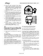
Figure 6.5


d)  When installing bearings on shaft, a slight heat is

required to expand the inner bearing race. The
use of a 150 watt (0.15 hp) light bulb with an
aluminium foil cover to contain the heat is
recommended. Place bulb foil to cover over
bearing and light bulb. Heat for approximately 20
- 30 minutes.

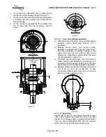
e)  Install the lock washer  and locknut.


Figure 6.6


f)  Place the bearing housing in a vertical position on

blocks in preparation for installation of shaft
assembly. Make sure blocking is of sufficient
height so that shaft will not contact the floor.

g) Suspend shaft vertically for installation into

bearing housing. Position oil ring (if fitted) on
shaft to prevent damage it enters bearing
housing.

h) Lower the shaft assembly into the bearing

housing. Install gasket and end cover.  Torque
bolts in accordance with Section 6.6.

Summary of Contents for HPXM

Page 1: ...gle stage single suction radially split volute type centrifugal pumps PCN 14983571 03 11 E Original instructions Installation Operation Maintenance These instructions must be read prior to installing operating using and maintaining this equipment ...

Page 2: ...4 6 Piping 20 4 7 Final shaft alignment check 22 4 8 Electrical connections 22 4 9 Protection systems 22 5 COMMISSIONING START UP OPERATION AND SHUTDOWN 22 5 1 Pre commissioning procedure 22 5 2 Pump lubricants 26 5 3 Direction of rotation 27 5 4 Guarding 27 5 5 Priming and auxiliary supplies 27 5 6 Starting the pump 28 5 7 Operating checks 28 5 8 Normal Start Up 29 5 9 Stopping and shutdown 29 5 ...

Page 3: ...rication schedule see 5 2 26 Maintenance 6 30 Maintenance schedule 6 2 30 Name nomenclature see 3 2 12 Nameplate 1 7 1 8 Operating limits see 3 4 14 Ordering of spares 6 3 1 32 Part assemblies 4 2 15 Parts lists see 8 40 Performance see 3 4 14 Piping 4 6 20 Pre commissioning procedure 5 1 22 Protection systems 4 9 22 Priming and auxiliary supplies 5 5 27 Reassembly see 6 9 35 Receipt and unpacking...

Page 4: ...le the Directives and any additional Approvals cover important safety aspects relating to machinery and equipment and the satisfactory provision of technical documents and safety instructions Where applicable this document incorporates information relevant to these Directives and Approvals To confirm the Approvals applying and if the product is CE marked check the serial number plate markings and ...

Page 5: ... the necessary knowledge and skill appropriate training and instruction must be provided If required the operator may commission the manufacturer supplier to provide applicable training Always coordinate repair activity with operations and health and safety personnel and follow all plant safety requirements and applicable safety and health laws and regulations 1 6 3 Safety action This is a summary...

Page 6: ...a action must be taken to avoid accidental contact If complete protection is not possible the machine access must be limited to maintenance staff only with clear visual warnings and indicators to those entering the immediate area Note bearing housings must not be insulated and drive motors and bearings may be hot If the temperature is greater than 80 C 175 F or below 5 C 20 F in a restricted zone ...

Page 7: ...re is with the plant operator Temperature classification Tx is used when the liquid temperature varies and when the pump is required to be used in differently classified potentially explosive atmospheres In this case the user is responsible for ensuring that the pump surface temperature does not exceed that permitted in its actual installed location If an explosive atmosphere exists during the ins...

Page 8: ...g or protecting the pump and ancillary systems Where there is the potential hazard of a loss of a seal barrier fluid or external flush the fluid must be monitored If leakage of liquid to atmosphere can result in a hazard the installation of a liquid detection device is recommended 1 6 4 7 Maintenance to avoid the hazard CORRECT MAINTENANCE IS REQUIRED TO AVOID POTENTIAL HAZARDS WHICH GIVE A RISK O...

Page 9: ...evel at some speeds Consult a Noise Specialist for the combined calculation For units driven by equipment other than electric motors or units contained within enclosures see the accompanying information sheets and manuals Typical sound pressure level dBA LB pAB at 1 m reference 20 μPa LB wAB sound power 1pW where LB pAB 85 dBA 3500 rpm 2900 rpm 1750 rpm 1450 rpm Motor size and speed kW hp Pump onl...

Page 10: ...nnel must carry out lifting in accordance with local regulations The driver and pump weights are recorded on general arrangement drawing included into the job user s instruction 2 3 1 To Lift unit Pump driver and baseplate can be lifted as a unit Sling from all four 4 eye bolts provided on baseplate side rails Failure to use all four 4 could result in permanent distortion of the baseplate Use as l...

Page 11: ...ions by heavy plastic sheets canvas waterproof burlap or other suitable coverings All equipment must be placed upon skids or blocks to prevent contact with the ground and surface contaminants Equipment must be adequately supported to prevent distortion and bending The pump shaft should be rotated in the direction of rotation at least 1 and 1 4 turns each week during the storage period and any othe...

Page 12: ...ecification Refer to FLOWSERVE for the description of paints and preservatives used on this order if needed 2 4 1 5 Associated equipment Motors Turbines Gears etc being supplied by FLOWSERVE Generally rotors of associated equipment should be blocked to relieve bearing loads Storage should be indoors and dry See the specific manufacturers storage requirements 2 5 Recycling and end of product life A...

Page 13: ... any foreign matter Special outsourced baring isolators are available as an option The standard bearing lubrication is provided by a shaft mounted metal slinger that transfers oil to bearing feed galleries within the housing wall Ring oil lubrication is optional Two metal slingers are positively locked on the shaft with set screws and bearing lubrication is provided by a heavy duty oil ring A plug...

Page 14: ... therefore to ensure the maximum pump working pressure is not exceeded the driver is not overloaded NPSHA NPSHR and that noise and vibration are within local requirements and regulations 3 4 4 Net Positive Suction Head NPSH Any liquid hot or cold must be pushed into the impeller of the pump by absolute pressure such as the atmospheric or vessel pressure from which the pump takes its suction The he...

Page 15: ...n initial alignment check in accordance with the alignment section of this document shall be performed to verify that coupling spacing and final alignment can be achieved without modifying the hold down bolts or the machine feet This is necessary to ensure that the baseplate was not damaged during the transportation 4 3 Foundation There are many methods of installing pump units to their foundation...

Page 16: ...screw furnished with the baseplate The purpose of the plate is to spread the load of the screw without crushing the concrete below Not supplied Figure 4 3 4 3 2 Method of levelling baseplate using wedges or shims a Level the baseplate by using a machinist s level on the machined surfaces of the pump and driver pads Levelling is best achieved by adjusting the shim pack thickness under each holding ...

Page 17: ...assure correct distribution of the grout Check to see that the grout flows under the edges of the baseplate evenly Do not vibrate baseplate when grouting making sure baseplate is vented correctly and all areas are thoroughly puddle to prevent any resonant problems When the grout is thoroughly hardened remove the dam and wedges if desired filling in the holes they leave with grout Pour grout until ...

Page 18: ...s and coupling Flexible couplings will not compensate for appreciable misalignment Foundation settling thermal expansion or nozzle loads resulting in baseplate foundation deflection and vibration during operation may require the full coupling misalignment capability 4 5 2 1 1 Types of misalignment There are two types of shaft misalignment angular and offset Therefore two sets of measurements and c...

Page 19: ...mum permissible misalignment at working temperature Parallel 0 05 mm 0 002 in TIR Angular 0 025 mm 0 001 in TIR Pumps with thick flanged non spacer couplings can be aligned by using a straight edge across the outside diameters of the coupling hubs and measuring the gap between the machined faces using feeler gauges measuring wedge or calipers When the electric motor has sleeve bearings it is neces...

Page 20: ...e condition Changes in the hydraulic system may affect performance adversely This is especially true if the changes reduce the pressure at the suction or if the liquid temperature is increased In case of doubt contact FLOWSERVE Suction and discharge piping should be of ample size be installed in direct runs and have a minimum of bends Double bends must be avoided in suction line and a straight run...

Page 21: ...hen the unit is being started the gauges on each side of the screen should be carefully watched An increase in the differential pressure between the two gauges indicates that the screen is becoming clogged with dirt and scale At this point the pump should be shut down and the screen cleaned and or replaced A spool piece should be installed in suction line so that the suction strainer may be instal...

Page 22: ...upplied within the terminal box including any temperature earth leakage current and other protective devices as appropriate The identification nameplate should be checked to ensure the power supply is appropriate A device to provide emergency stopping must be fitted If not supplied pre wired to the pump unit the controller starter electrical details will also be supplied within the controller star...

Page 23: ...to the bearing housing provided by oil ring slinger or pure oil mist A constant level oiler is normally furnished except for pure oil mist lubrication with the pump unless otherwise specified 5 1 1 1 Oil ring or Slinger Lubrication Before filling the bearing housing reservoir flush out the housing thoroughly with safety solvent and a leading grade of flushing oil compatible with the lubricating oi...

Page 24: ...ablish a measurement from the centre line of the oiler connection in bearing housing to the upper cross arm of 6 mm 0 24 in this can be obtained by completely screwing down the lower arm as illustrated on figure 5 3 c Fill bottle with recommended oil and install on holder Remove and fill bottle as many times as is required to fill the bearing housing up to the cross arm level and no air bubbles ap...

Page 25: ...rust bearings NPT vent connection in the space between the rolling element bearing and the inboard outboard bearing housing cover NPT drain connection in the bottom half of the bearing housing Remove inlet and outlet pipe plugs from above connections Install appropriate reclassifier in the top opening leave open vent connections connect oil recovery trap to bottom opening or leave it open to act a...

Page 26: ...L46 Anstron HLP46 Anstron HL68 Anstron HLP68 Elf OLNA 32 HYDRELEF 32 TURBELF 32 ELFOLNA DS32 TURBELF SA46 ELFOLNA DS46 TURBELF SA68 ELFOLNA DS68 Esso TERESSO 32 NUTO H32 TERESSO 46 NUTO H46 TERESSO 68 NUTO H68 LSC for oil mist LSO 32 Synthetic oil LSO 46 Synthetic oil LSO 68 Synthetic oil LSO 100 Synthetic oil Mobil Mobil DTE oil light Mobil DTE13M MobilDTE24 Mobil DTE oil medium Mobil DTE15M Mobi...

Page 27: ...ting temperature is below 10 C 14 F for long time it s suggested to use synthetic oil Other drivers and gearboxes if appropriate should be lubricated in accordance with their manuals In the case of product lubricated bearings the source of product supply should be checked against the order There may be requirements for an external clean supply particular supply pressure or the commencement of lubr...

Page 28: ... pump recirculating line if required is open clear and free of obstructions g Check that pump is vented by observing leakage from casing vent when fitted and seal piping vent Close vent if fitted when liquid is emitted h Turn on cooling liquid and assure correct flow exists to cooler insert gland etc as specified i Double check pump rotation by starting unit momentarily The direction of input shaf...

Page 29: ...nsor is provided set the alarm at 93 C 180 F and the trip at 105 C 200 F It is important to keep a check on bearing temperatures After start up the temperature rise should be gradual reaching a maximum after approximately 1 5 to 2 hours This temperature rise should then remain constant or marginally reduce with time 5 7 4 Normal vibration levels alarm and trip For guidance pumps generally fall und...

Page 30: ...guard rails are required for maintenance they must be placed for easy access to areas where maintenance and inspection are to be carried out The positioning of these accessories must not limit access or hinder the lifting of the part to be serviced When air or compressed inert gas is used in the maintenance process the operator and anyone in the vicinity must be careful and have the appropriate pr...

Page 31: ...ectly i Check stand by pump is at applicable temperature and available to start as required Refer to the manuals of any associated equipment for routine checks needed 6 2 2 Periodic inspection monthly a Check for lubricant contamination whether bearing oil or seal oil if applicable by sample analysis b Check all paint or protective coatings c Check all power instrument cable glands for tightness R...

Page 32: ...normal maintenance 1 set of bearings line and thrust 2 sets of gaskets and o ring 1 mechanical seals 1 labyrinth and deflector set drive and impeller end 1 shaft 1 impeller 6 5 Tools required A typical range of tools that will be required to maintain these pumps is listed below Readily available in standard tool kits and dependent on pump size Open ended spanners wrenches to suit up to 2 M 50 scre...

Page 33: ...not necessary to remove casing or to detach suction or discharge piping coupling hubs or to remove driver a Remove all seal piping related instrumentation and electrical equipment that will interfere with disassembly Drain pump casing When pump is handling hot liquid extreme care must be taken to ensure safety of personnel when attempting to drain pump Hot pumps must be allowed to cool before drai...

Page 34: ... ring h Remove mechanical seal cartridge assembly Refer to any special instructions supplied with the mechanical seal 6 7 1 2 Bearing housing disassembly a Looking at the bearing housing remove impeller key and throat bush if fitted If a cooling fan is fitted then remove the three locking screws securing the fan to the outboard deflector Withdrawal the fan from the coupling end of the shaft b Loos...

Page 35: ...l it is clean Rinse in a clean container of fresh solvent Do not spin dirty bearings Rotate them slowly while washing d Dry thoroughly cleaned bearings If an air hose is used for drying make sure it is clean dry air Do not allow the bearings to spin by force of air Hold the inner and outer rings to prevent bearing from spinning e Inspect bearings immediately If there is any question as to the cond...

Page 36: ... without special gloves Care must be taken to keep the bearing clean and uncontaminated The old and once popular method of heating bearings in an oil bath is DEFINITELY DISCOURAGED HEATING INNER RING WITH A GAS TORCH IS PROHIBITED In either case it is difficult to control the heating rate and final temperature and even more difficult to keep the oil and or bearing clean c When bearings are install...

Page 37: ...ing plates from transit to run position Refit screwed piping into mechanical seal gland plates Refer to any special instructions supplied with the mechanical seal 6 9 4 Casing assembly a For non inducer machines install key and impeller Install locking nut noting left hand thread form Torque nut to correct tightness Fit and tighten lockscrew on end of locknut throat bush if fitted b Install a new ...

Page 38: ...rough mechanical seal sleeve joints casing joint or pipe plugs Check and replace faulty parts CONSULT FLOWSERVE z z Foot valve too small Investigate replacing the foot valve z z Foot valve partially clogged Clean foot valve z z z z Inlet of suction pipe insufficiently submerged Check out system design z z z Speed too low CONSULT FLOWSERVE z Speed too high CONSULT FLOWSERVE z z z Total head of syst...

Page 39: ...er out of balance resulting in vibration z z z Abrasive solids in liquid pumped z z Internal misalignment of parts preventing seal ring and seat from mating properly Check and CONSULT FLOWSERVE z z Mechanical seal was run dry Check mechanical seal condition and source of dry running and repair z z Internal misalignment due to improper repairs causing impeller to rub Check method of assembly possib...

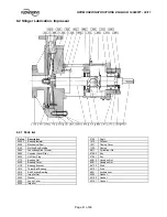
Page 40: ...over 3130 Beating Bracket 3013 Thrust Ball Bearing 3010 Anti Friction Bearing 2912 Impeller Nut 2905 Washer 2540 2 Deflector 2540 1 Deflector 2520 Loose Collar 2200 Impeller 2100 Shaft 1410 Diffuser 1221 Casing Cover 1100 Casing 6811 Cylindrical Pin 6700 2 Key 6700 1 Key 6581 2 Hexagon Nut 6581 1 Hexagon Nut 6572 2 Stud 6572 1 Stud 6541 Lockwasher 4610 2 O Ring 4610 1 O Ring 4590 Gasket 4510 2 Gas...

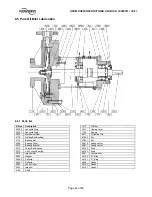
Page 41: ...3855 Constant Level Oiler 3854 Oil Filter Plug 3712 Bearing Nut 3260 Bearing Cover 3130 Bearing Bracket 3013 Thrust Ball Bearing 3010 Anti Friction Bearing 2912 Impeller Nut 2905 Washer 2520 Loose Collar 2200 Impeller 2100 Shaft 1410 Diffuser 1221 Casing Cover 1100 Casing 6811 Cylindrical Pin 6700 2 Key 6700 1 Key 6581 2 Hexagon Nut 6581 1 Hexagon Nut 6572 2 Stud 6572 1 Stud 6541 Lockwasher 4590 G...

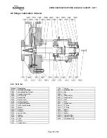
Page 42: ...g Bracket 3013 Thrust Ball Bearing 3010 Anti Friction Bearing 2912 Impeller Nut 2905 Washer 2540 2 Deflector 2540 1 Deflector 2520 Loose Collar 2200 Impeller 2100 Shaft 1410 Diffuser 1221 Casing Cover 1100 Casing 6811 Cylindrical Pin 6700 2 Key 6700 1 Key 6581 2 Hexagon Nut 6581 1 Hexagon Nut 6572 2 Stud 6572 1 Stud 6550 Cooling Device 6541 Lockwasher 4610 2 O Ring 4610 1 O Ring 4590 Gasket 4510 2...

Page 43: ...aring Bracket 3013 Thrust Ball Bearing 3010 Anti Friction Bearing 2912 Impeller Nut 2905 Washer 2540 2 Deflector 2540 1 Deflector 2520 Loose Collar 2200 Impeller 2100 Shaft 1410 Diffuser 1221 Casing Cover 1100 Casing 8161 Fan 6811 Cylindrical Pin 6700 2 Key 6700 1 Key 6581 2 Hexagon Nut 6581 1 Hexagon Nut 6572 2 Stud 6572 1 Stud 6541 Lockwasher 4610 2 O Ring 4610 1 O Ring 4590 Gasket 4510 2 Gasket...

Page 44: ...t 3260 Bearing Cover 3130 Bearing Bracket 3013 Thrust Ball Bearing 3010 Anti Friction Bearing 2912 Impeller Nut 2905 Washer 2540 2 Deflector 2540 1 Deflector 2520 Loose Collar 2200 Impeller 2100 Shaft 1410 Diffuser 1221 Casing Cover 1100 Casing 6811 Cylindrical Pin 6700 2 Key 6700 1 Key 6581 2 Hexagon Nut 6581 1 Hexagon Nut 6572 2 Stud 6572 1 Stud 6541 Lockwasher 4610 2 O Ring 4610 1 O Ring 4590 G...

Page 45: ...30 Bearing Bracket 3013 Thrust Ball Bearing 3010 Anti Friction Bearing 2905 Washer 2540 2 Deflector 2540 1 Deflector 2520 Loose Collar 2215 Inducer 2200 Impeller 2100 Shaft 1410 Diffuser 1221 Casing Cover 1100 Casing 6811 Cylindrical Pin 6700 2 Key 6700 1 Key 6581 2 Hexagon Nut 6581 1 Hexagon Nut 6572 2 Stud 6572 1 Stud 6541 Lockwasher 4610 2 O Ring 4610 1 O Ring 4590 Gasket 4510 2 Gasket 4510 1 G...

Page 46: ...ry User Instruction manuals Supplementary instruction determined from the contract requirements for inclusion into User Instructions such as for a driver instrumentation controller sub driver seals sealant system mounting component etc are included under this section If further copies of these are required they should be obtained from the purchaser for retention with these User Instructions 10 2 C...

Page 47: ...HPXM USER INSTRUCTIONS ENGLISH 14983571 03 11 Page 47 of 48 NOTES ...

Page 48: ...03 4434 Fax 1 713 803 4497 Asia Pacific Flowserve Pte Ltd 10 Tuas Loop Singapore 637345 Telephone 65 6771 0600 Fax 65 6779 4607 Local Flowserve factory representatives To find your local Flowserve representative please use the Sales Support Locator System found at www flowserve com Your Flowserve factory contacts Service Warranty Flowserve Flow Solutions Group Italy Worthington S r l Via Rossini 9...

Reviews: