HWMA2 USER INSTRUCTIONS ENGLISH - 06/16
Page 29 of 39
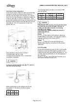
6.6 Setting impeller clearance
For axial rotor setting see section 5
Commissioning
startup, operation and shutdown.
6.7 Disassembly
Refer to section 1.6,
Safety
, before
dismantling the pump.
Before dismantling the pump for
overhaul, ensure genuine Flowserve replacement
parts are available.
Refer to sectional drawings for part numbers and
identification.
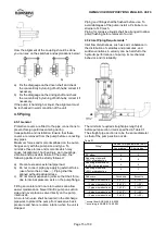
6.7.1 Dismantling of pump
1) Remove the coupling guards [7450] and secure the
mechanical seal by putting the setting plates into
the groove of the shaft sleeve. Loose the drive
collar to prepare further disassembly.
Refer to mechanical seal drawing for
details.
Drain the seal system, if
applicable.
2) Uncouple the motor from the pump and take off the
motor.
3) Loose the hexagon head bolt [6577.1] and pull off
the bearing lantern [3140].
4) Loose the hex nut [6572.2] and pull out the pump
assembly from the casing. Eventually use hexagon
head bolt [6577.2] to support this.
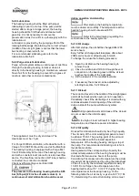
6.7.2 Dismantling of hydraulic section
1) Loose the impeller nut [2912] (right hand thread)
If the pump is equipped with an
inducer [2215] loose inducer.
2) Pull the 1
st
impeller from the shaft. As the impeller
is fitted relatively strong on the shaft, use as
support the two threads on the shroud of the
impeller.
3) After loosing the socket head cap screws [6579.1] ,
it is possible to remove the interstage plate [1471]
of the pump casing cover [1221].
4) Remove bearing sleeve [3400] and second
impeller from the shaft.
5) Remove the liner [1649] of the pump casing cover
[1221].
6.7.3 Dismantling for changing the mechanical seal
1) Loose studs [6572.3] and pull off pump casing
cover [1221] including mechanical seal cartridge.
2) Loose hex nuts [6581.4] to remove mechanical
seal cartridge from pump casing cover [1221].
6.7.4 Dismantling of the bearing housing
1) Loose the hexagon head bolt [6577.3] and pull off
the stuffing box housing [4110].
2) Pull off the deflector [2540] from the shaft after
loosing the grub screw [6814.2].
3) Unsecure shaft nut [2910] by loosing the cap
screw [6579.3].
4) Unscrew the shaft nut [2910], the hexagon head
bolt [6577.4] and remove the bearing cover
[1220] and [3260]. Take care about labyrinth ring
[4330].
5) Now you can pull out the shaft assembly from the
bearing housing. Pull off the bearing adaptor
sleeve [2471].
Take care of the key
[6700.3].
6) To pull off the angular contact bearings unsecure
lockwasher [6541.2] and loose bearing lock nut
[3712].
7) Pull off the distance sleeve [2460], the pumping
ring [4223] and the radial ball bearing [3011].
Take care of the key
[6700.2].
6.8 Examination of parts
1) Check whether any part of pump casing or impeller
was damaged by corrosion or erosion. Liquid
channels have to be clean and clear.
2) All liquid channels must be cleaned and free of rust
and mud on impeller! If machining of any impeller is
necessary it must be rebalanced dynamically after
this work. The balancing of the impellers is Q 2,5
according ISO 1940.
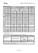
3) Check the total run out of the shaft when mounted.
The maximum allowable value is 0,05 mm
measured on the fit of the impeller.
4) Especially by pumping aggressive media pay
attention to chemical corrosion on the surfaces of
shaft and sleeve which are touched by the liquid.
The shaft sleeves must have a clean and even
surface at the area of the rotating unit of the
mechanical seal, otherwise it will fail in operation.
5) Defective shafts and sleeves shall be replaced if a
machining is impossible (in accordance with
tolerances respectively with run-out of shaft).
6) Check the inner surface of the impeller hub, the
impeller must have a proper fit on the shaft! Any
loose impeller will cause vibrations and destroy
shaft and bearings. The fit between shaft and
impeller hub is Ø38 G5/h5 ISO.
7) All defective seals respectively O-rings have to be
replaced.
8) At a complete overhaul of the pump all seals and
O-rings should be renewed depending on the

