HWMA2 USER INSTRUCTIONS ENGLISH - 06/16
Page 32 of 39
temperature may be observed during the run in
period.
The faces of the inner mechanical seal are flushed by
the product (API Plan11). In Plan 11, product is
routed from the pump discharge via an orifice to the
seal chamber to provide cooling for the seal and to
vent air or vapors from the seal chamber. Fluid then
flows from the seal cavity back into the process
stream. Between the inner mechanical seal and the
outer (atmospheric) mechanical seal is a liquid buffer
fluid, which is unpressurized (API Plan 52). The
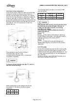
buffer fluid is contained in a seal pot (refer to drawing
of the seal pot), which is vented to a vent system,
thus maintaining the buffer fluid pressure close to
atmospheric.
Inner seal leakage will be product leakage into the
buffer fluid. There will always be some leakage
(max.5 ml/hour).
Plan 52 is used for flashing liquids, which have a
vapour pressure higher then the buffer fluid pressure.
So the product will flash in the seal pot and the
vapour can escape to the vent system.
All screw / flange connections have to be proofed.
Straight screw joints made of stainless steel have to be
tightened especially carefully.
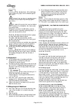
Fill the seal system with a suitable
buffer fluid (refer to lubrication table).
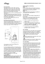
Ensure that the valve GV for the
connection V is open (Barrier/buffer fluid vessel
drawing).
Open the Block & Bleed valve to
allow proper function of the PSH (set point 0.5 bar
(7.25 psi) above flare pressure).
Open all necessary valves in the
cooling and auxiliary piping and check the flow.
Disassembly of the seal cartridge
is only allowed by authorized personal. Contact
Flowserve for any service of the mechanical seal. We
recommend to have a spare cartridge seal on stock
for easy replacement.
7.1.4 Single Mechanical Seal with API–Plan 23+61
Refer to mechanical seal drawing and
auxiliary piping drawing.
The pump is equipped with a single mechanical seal.
The cartridge design allows to change the
mechanical seal without taking it apart.
Actions before first start up:
The pump will be delivered with correct vertical
adjustment of the rotor.
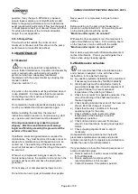
Try to turn the rotor by hand.If
the rotor cannot be turned readjust it following
procedure in section 5.3.1
Adjusting of the rotor.
The mechanical seal requires no adjustment
anymore. Check if the mounting plates are
alreadyswung out.
Actions after start up:
Check all connections to the seal gland and the
mechanical seal itself against leakage. It is usual that
at the seal faces a small leakage occurs after start
up, which decreases with the time of operation and
should stop after the seal is run in. Check the
temperature of the seal gland. I slight increase of
temperature may be observed during the run in
period. The mechanical seal is flushed by an API
Plan 23 and the temperature at the seal gland should
be below the pumped liquid temperature (refer to
mechanical seal drawing for temperature limit).
Plan 23 is the plan of choice for all hot water
services, and it is also disirable in many hydrocarbon
and chemical services where it is necessary to cool
the fluid establish the required margin between fluid
vapor pressure (at the seal chamber temperature)
and seal chamber pressure. In a Plan 23, the cooler
only removes seal face-generated heat plus heat
soak from the process. The seal chamber is isolated
by a pump throat bushing with a bypass to suction.
API Plan 61 has tapped and plugged connections for
the purchaser´s use. Typically this plan is used when
the purchaser is to provide fluid (such as steam, gas, or
water) to an external sealing device.
Refer to the GA - drawing for the
required quench medium, pressure and flow.
Disassembly of the seal cartridge
is only allowed by authorized personal. Contact
Flowserve for any service of the mechanical seal. We
recommend to have a spare cartridge seal on stock
for easy replacement.
7.1.5 Dual Mechanical Seal pressurized with
API–Plan 53b
Refer to mechanical seal drawing and
auxiliary piping drawing.
The pump is equipped with a dual mechanical seal in
face to back configuration, back to back configuration
or face to face configuration.


