HWMA2 USER INSTRUCTIONS ENGLISH - 06/16
Page 22 of 39
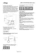
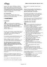
take into consideration that all bearings will have
higher temperatures during the first 20 service hours.
In constant operation the bearing temperature will
decrease about 10 °C (50 °F). The oil temperature
shall be lower than 85 °C (185 °F) after this running-
in time. The bearing outer race temperature should
not exceed 95°C (204°F). If the temperature is higher,
the reason may be a wrong oil quality, wrong oil level
or overload of the pump because of excessive wear.
If the humidity at the site is high, the roller bearings
become easily rusty during stand still periods. To
avoid that, we recommend to mix the lubricating oil
with a corrosion inhibitor contact your lubrication oil
supplier for proper additives inhibitors.
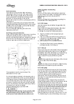
5.2.13 Oil quantity
To fill the bearing housing to middle of the oil sight
glass a amount of approximately 40 oz. (1.2l) is
required.
5.3 Impeller clearance
Correct axial rotor setting is essential for trouble free
operation of the pump.
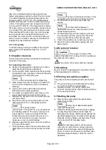
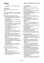
5.3.1 Adjusting of the rotor
a) Remove coupling spacer, coupling hub on pump
shaft and fan [8161] (when delivered).
b) Fix the position of the mechanical seal by putting
the assembly jigs, mounted on the seal end plate,
into the groove in the shaft sleeve.
No requirements for softpacking,
c) Open screws from the clamping unit, located on
the end of the shaft sleeve (refer to shaft seal
drawing).
d) Loose and remove socket head cap screws
[6579.3] from the shaft nut [2910].
e) Turn shaft nut upside till the rotor moves in the
lowest position and cannot turned by hand.
f) Measure the dimension from the shaft nut to the
end of the shaft.
g) Now lift the rotor by turning the shaft nut in the
other direction till it is in the highest position.
For heavy pumps
(rotor weight > 150 kg (331 lb.)) we recommend
the following practice. The rotor is already in its
lowest position. Screw in an Eyebolt into the
thread at the top of the shaft. Use a lever or a
crane to lift the shaft (do it slowly, the axial
clearance is only a few millimetres).
h) Measure again the dimension from the shaft nut
to the end of the shaft.
i) Take the mean value of the two dimensions and
adjust the rotor to this value by turning the shaft
nut.
The type of hydraulic is shown on the
nameplate (refer to section 3.2
Nomenclature
)
j) Fix the shaft nut with the socket head cap
screws.
Turn the shaft nut always in
downwards direction to meet the whole for the
socket head cap screw.
k) Fix the shaft sleeve with the clamping unit and
turn the tools out of the groove from the shaft
sleeve and fix them on the seal end plate.
l) Check if the shaft can be turned easy by hand
m) Mount fan (when delivered) coupling hub and
spacer again.
5.4 Direction of rotation
The sense of rotation of the
pump is clockwise (CW); looking from the coupling to
the shaft end of the pump.
The rotation of the driver shall be checked.
5.5 Guarding
Be sure that the coupling guard is mounted correctly
at the baseplate prior to start up.
5.6 Priming and auxiliary supplies
The pump must be completely primed prior to start
up.
a) The pump casing is considered as self venting,
so no vent connections are provided.
b) Auxiliary systems, e.g. barrier /buffer fluid
systems, cooling circuits, shall be filled according
to the user instructions.
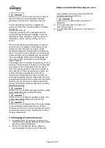
5.7 Starting the pump
a) Start the driver according to the specification.
(Refer to driver IOM).
Pumps are usually started against
closed discharge valve.
b) Check the discharge and suction pressure gauge
to verify the pumps delivered head. Open the
discharge valve slowly, until the pump reaches the
specified operation point. The pump must operate
smoothly, and the vibration must be below 5 mm/s
(0.2 in./sec) (API 610 vibration limits).
The discharge valve must be opened
within 30 sec. after start up. Longer operation
against closed discharge valve will damage the
pump. If a minimum flow valve is installed, take
pressure gauge readings to verify the correct
operation.

