HWMA2 USER INSTRUCTIONS ENGLISH - 06/16
Page 33 of 39
Try to turn the rotor by hand. If
the rotor cannot be turned readjust it following
procedure in section 5.3.1
Adjusting of the rotor.
The mechanical seal requires no adjustment
anymore. Check if the mounting plates are already
swung out.
Actions after start up:
Check all connections to the seal gland and the
mechanical seal itself against leakage. Check the
temperature of the seal gland. I slight increase of
temperature may be observed during the run in
period.
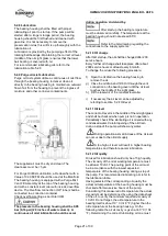
Plan 53 pressurized dual seal systems are used in
services where no leakage to atmosphere can be
tolerated. A Plan 53b system consists of dual
mechanical seals with a liquid barrier fluid between
them. The barrier fluid is contained in a seal pot and
is pressurized by using a bladder type accumulator.
Inner seal leakage will be barrier fluid leakage into
the product. There will always be some leakage
(max.5 ml/hour).
The leakage rate is monitored by monitoring the seal
pot level. The product must be able to accommodate
a small amount of contamination from the barrier
fluid. The seal pot pressure must be maintained at
the proper level. If the seal pot pressure drops, the
system will begin to operate like a Plan 52, or
unpressurized dual seal, which does not offer the
same level of sealing integrity. Specifically, the inner
seal leakage direction will be reversed and the barrier
fluid will, over time, become contaminated with the
process fluid with the problems that result, including
possible seal failure.
Fill the seal system with a suitable
barrier buffer fluid (refer to lubrication table).
Open all necessary valves in the
cooling and auxiliary piping and check the flow.
Disassembly of the seal cartridge
is only allowed by authorized personal. Contact
Flowserve for any service of the mechanical seal. We
recommend to have a spare cartridge seal on stock
for easy replacement.
7.2 Changing of mechanical seal
1) Completely drain the pump by using the drain
connection. By pumping explosive or toxic media,
flush the system with Nitrogen.
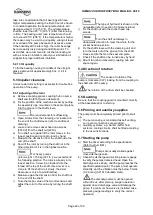
2) Secure the mechanical seal by putting the
mounting plates into the groove of the shaft
sleeve [2450]. Loose the grub screws [6814.4],
and disconnect the seal piping.
Drain the seal system, if
applicable.
3) For disassembly refer to section 6.7.1,
Dismantling of pump
.
4)
For assembly refer to section 6.9.1,
Assembly of
pump

