IJ PUMP OPERATION AND MAINTENANCE MANUAL
3-15
BO2660-01
3.2.4 BASEPLATE FOR PUMP OR SINGLE UNIT
To level a baseplate that is used only for the pump or a single unit, select the applicable method
below:
1. Verify that baseplate is aligned to a common centerline with other baseplates (or soleplates) in
train as instructed by steps 1 through 6 under BASEPLATES (OR SOLEPLATES) IN
TRAIN above.
2. First method (using optical alignment equipment, level baseplate on shims or leveling screws)
within nominal leveling gradient (0.001 inch per 12 inches (0.03 mm per 305 mm)). Then
tighten down anchor nuts and recheck for nominal gradient. If baseplate is not level, loosen
anchor nuts, relevel it, retighten nuts, and check for nominal gradient. Continue this process
until the baseplate is anchored and level.
3. Second method (using machinist level) proceed as follows:
a. Determine high end of baseplate. Then start leveling across mounting pads at high end by
adding or removing shims at, or adjusting leveling screws at, anchor bolts below
mounting pad that you are leveling. Continue leveling until baseplate is level in crosswise
direction as shown in LEVELING PUMP END CROSSWISE figure, if pump is on
baseplate, or in LEVELING DRIVER END CROSSWISE figure, if pads are vacant.
b. Level both sides of baseplate in lengthwise direction by removing shims at, or adjusting
leveling screws at, anchor bolts below mounting pad that you are leveling. Continue
leveling until both sides of baseplate are level at places shown in LEVELING PUMP
END LENGTHWISE figure, if pump is on baseplate, or in LEVELING DRIVER END
LENGTHWISE figure, if pads are vacant.
c. Tighten foundation anchor bolts and pump feet holddown bolts, if pump is installed. As
you tighten bolts, position level as illustrated in the two figures that are referred to in the
steps above and check leveling in both crosswise and lengthwise directions. If tightening
bolts disturbs leveling, loosen bolts and shim or adjust leveling screws until baseplate is
level in both directions at places where leveling was disturbed. Again tighten bolts and
verify leveling in both directions. Continue this procedure until all holddown bolts are
tight and baseplate is level; both crosswise and lengthwise.
d. Complete steps 8 through 10 under BASEPLATES (OR SOLEPLATES) IN TRAIN
above; then grout baseplate as described under GROUTING.
3.2.5 LEVELING SOLEPLATES.
When leveling soleplates the main points to remember are:
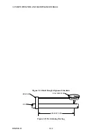
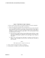
1. The OUTLINE drawing, and ALIGNING AND LEVELING SOLEPLATES figure illustrate
the dimensions and placement of the soleplates.
2. Anchor bolts and nuts must be recessed in the soleplates as shown on the OUTLINE drawing.
3. The foundation such as described under PREINSTALLATION, requires ample curing time
before it can support the weight of soleplates and pump.
4. A minimum space of 1 in (25 mm) is required between soleplate and foundation to assure
sufficient grouting. This may be obtained by placing shims adjacent to each foundation bolt
hole or beneath each leveling screw in the baseplate.
5. Soleplates must be precisely leveled in a common plane, both lengthwise and crosswise,
using a machinist level or a more precision tool.
Summary of Contents for IJ
Page 2: ...IJ PUMP INSTALLATION OPERATION MAINTENANCE ...
Page 3: ......
Page 5: ...IJ PUMP OPERATION AND MAINTENANCE MANUAL BO2660 01 iv ...
Page 11: ...IJ PUMP OPERATION AND MAINTENANCE MANUAL BO2660 01 x ...
Page 13: ...IJ PUMP OPERATION AND MAINTENANCE MANUAL BO2660 01 xii ...
Page 17: ...IJ PUMP OPERATION AND MAINTENANCE MANUAL BO2660 01 xvi ...
Page 25: ......
Page 35: ...IJ PUMP OPERATION AND MAINTENANCE MANUAL BO2660 01 2 10 Figure 2 1 Foundation Bolt ...
Page 65: ......
Page 79: ......
Page 83: ......


