IJ PUMP OPERATION AND MAINTENANCE MANUAL
BO2660-01 4-8
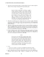
7. Check lube oil inlet temperature indicator of pump bearings and driver and outlet temperature
indicator of heat exchanger; readings should be approximately same.
NOTE
Because heat that is generated by a bearing is constant, a
change in ambient temperature may require additional
cooling of the bearings. That is, when the ambient or cooling
water temperature is hotter than usual, it may be necessary
to increase the flow of cooling water through the lube oil
heat exchanger in order to decrease the temperature of the
lube oil, and also to adjust the pressure reducing valve
(PRV) to maintain the prescribed system pressure; but
adjustment, in each case, shall be such that the lube oil
temperature, flow, and pressure at the bearings of the pump
is as specified in the OPERATING SPECIFICATIONS.
8. Check lube oil discharge pressure indicators (PI) that are located in piping immediately
downstream of pressure reducing valve (PRV) and in instrument panel; indicators should read
inlet pressure of lube oil at pump bearings and driving units as given in OPERATING
SPECIFICATIONS.
9. Check lube oil discharge pressure indicators (PI) that is located immediately downstream of
main lube oil pump; indicator should read setting given in lube oil console manufacturer's
data (see APPENDIX) for back pressure control valve (PCV). If reading is off, adjust valve
so that indicator reads given setting. The other indicator should read zero. For information on
valve, see valve manufacturer's instructions in APPENDIX.
10. In step 8, if discharge pressure indicator (PI) did not read inlet pressure of lube oil at bearings
of pump and driving units as given in OPERATING SPECIFICATIONS, adjust pressure
reducing valve (PRV) so that indicators read specified inlet pressure. For information on
valve, see valve manufacturer's instructions in APPENDIX.
NOTE
If the pressure of the main lube oil pump decreases below
the required pressure (see OPERATING SPECIFICATIONS)
the low lube oil pressure switch (PS) should activate an
alarm, and if pressure continues to decrease the auxiliary or
spare lube oil pump pressure switch (PS) should activate to
energize the spare or auxiliary lube oil pump and the main
lube oil pump should shut down. An additional pressure
switch (PS) is incorporated to deenergize power to driver
should both lube oil pumps lose pressure (see lube oil
console manufacturer's data in APPENDIX).
11. Verify:
a. that flow rate of pump is as specified under OPERATING SPECIFICATIONS;
b. that lube oil system, cooling system, and seal flush system do not evidence leakage.
12. Observe differential pressure indicator of differential pressure and switch unit (PDI-PDSH) or
differential pressure indicator (PDI), whichever is applicable (see lube oil console
Summary of Contents for IJ
Page 2: ...IJ PUMP INSTALLATION OPERATION MAINTENANCE ...
Page 3: ......
Page 5: ...IJ PUMP OPERATION AND MAINTENANCE MANUAL BO2660 01 iv ...
Page 11: ...IJ PUMP OPERATION AND MAINTENANCE MANUAL BO2660 01 x ...
Page 13: ...IJ PUMP OPERATION AND MAINTENANCE MANUAL BO2660 01 xii ...
Page 17: ...IJ PUMP OPERATION AND MAINTENANCE MANUAL BO2660 01 xvi ...
Page 25: ......
Page 35: ...IJ PUMP OPERATION AND MAINTENANCE MANUAL BO2660 01 2 10 Figure 2 1 Foundation Bolt ...
Page 65: ......
Page 79: ......
Page 83: ......

