flowserve.com
8 Main
8.1 Drive
The driver mo
means of a dif
is routed to th
flexible hose.
the driver mod
assembly con
modulator to t
Driver Modul
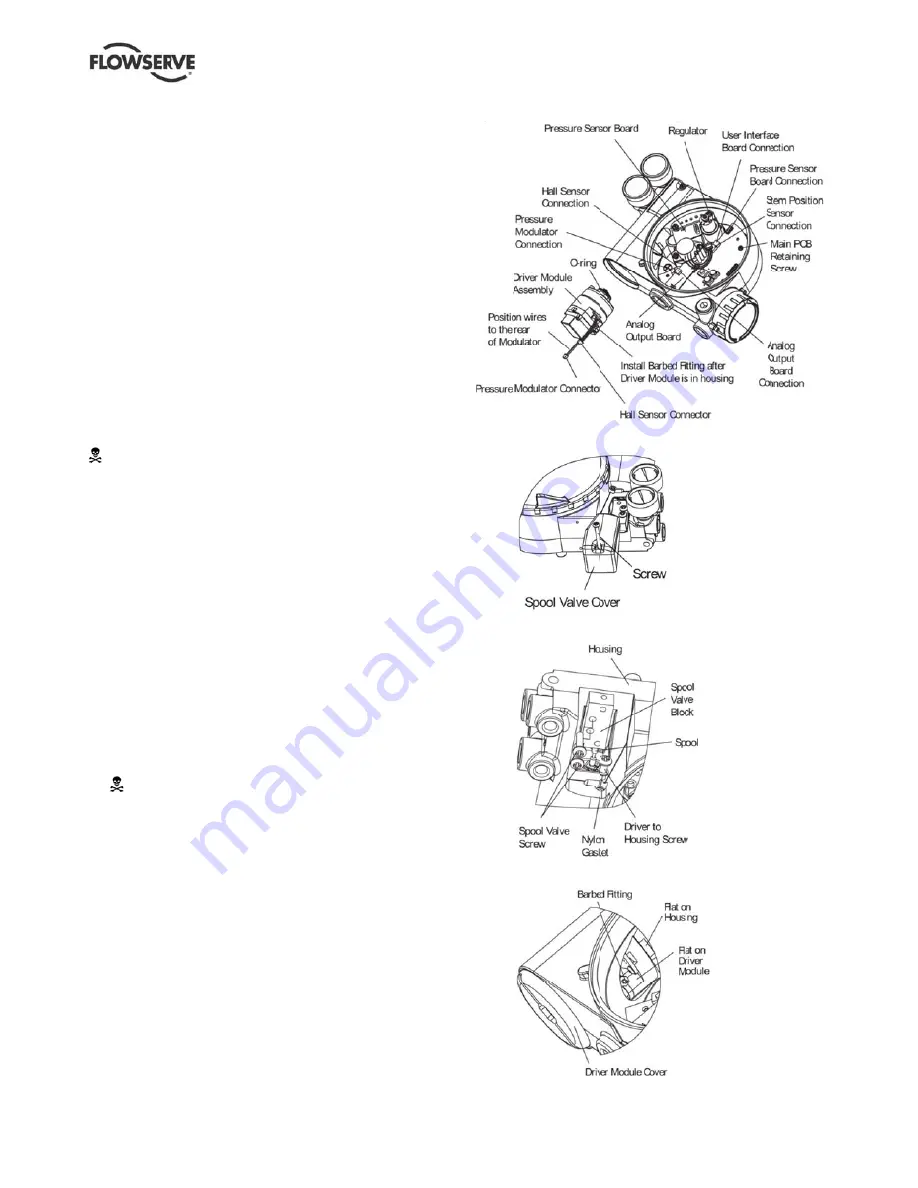
To replace the
11-15 and 25
following tools
Flat
plate
Phillips
sc
1
/
4
in. nut
WARNING
electrostat
1. Make sure
2. Disconnec
3. Remove th
bar or plat
4. Remove th
and sliding
is clear of
hydrophob
the spool v
parts out o
5. Being care
Phillips-he
the main h
WARN
assem
when h
handle
The tol
extrem
the spo
6. Remove th
Phillips-he
the spool (
7. Carefully r
spool out o
bend spoo
8. Remove th
ntenance
er Module A
odule assembly
fferential press
e driver module
A barbed fittin
dule assembly.
nect the hall ef
the main PCB a
e Assembly R
e driver module
and proceed a
s are required:
or bar about
1
/
crewdriver
tdriver
G:
Observe pre
tically sensitive
e the valve is by
ct the power an
he driver modu
e in the slot to
he spool valve
g the cover ass
the slot (figure
bic filter, and O
valve cover. It
of the spool val
eful not to lose
ead screw that
housing (figure
NING:
Spool (ex
bly) is easily da
handling spool
e the spool by t
lerances betwe
mely tight. Cont
ool may cause
he spool valve
ead screws and
(figure 13).
remove the spo
of the connecti
ol.
he main cover.
and Repa
Assembly
y moves the sp
sure across its
e from the regu
ng connects the
Wires from th
ffect sensor an
assembly.
Replacement
e assembly, ref
as outlined belo
/
8
in. thick
ecautions for ha
e devices.
ypassed or in a
nd air supply to
le cover (figure
turn the cover.
cover by remo
sembly backwa
12). The shee
-ring should be
is not necessa
ve cover.
the nylon wash
attaches the dr
13).
xtending from t
amaged. Use
l and spool valv
he machined p
een the block a
tamination in th
the spool to ha
block by remov
d carefully slidin
ool by sliding th
on clip. Exces
Use
air
ool valve by
diaphragm. Ai
ulator through a
e flexible hose
he driver modu
nd the piezo va
fer to figures
ow. The
andling
a safe condition
the unit.
e 14), using a f
.
oving the screw
ards until the ta
et metal cap,
e removed with
ary to take thes
her, remove th
river module to
the driver modu
extreme cautio
ve block. Do n
portions of spoo
and spool are
he block or on
ang.
ving the two
ng the block off
he end of the
ssive force may
er instructions
r
a
to
le
lve
n.
flat
w
b
h
se
e
o
ule
on
not
ol.
f
y
Figure
Figure
Figure
Figure
– Digital Positi
11: Driver Mod
12: Spool Valv
13: Spool and
14: Driver Mod
ioner 3200MD
dule Assembly
ve Cover Assem
Block
dule Barbed Fit
LGENIM0059
mbly
tting
9-04 09/11
21


