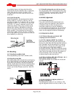
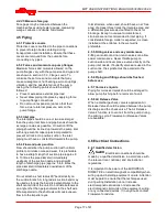
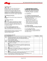
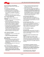
background image

MPT USER INSTRUCTIONS ENGLISH 85392699 06-09 


Page 12 of 41 

®

The pump may be stored as above for up to 6 
months.  Consult Flowserve for preservative actions 
when a longer storage period is needed. 
 
2.4.1  Storage – General 
Normal packaging is designed to protect the pump 
and parts during shipment and for dry, indoor 
storage for up to six months or less.  The following is 
an overview of our normal packaging: 


All loose unmounted items are packaged in a 
water proof plastic bag and placed under the 
coupling guard 


Inner surfaces of the bearing housing, shaft (area 
through bearing housing) and bearings are coated 
with Cortec VCI-329 rust inhibitor, or equal. 

 Bearing housings are not filled with oil 

prior to shipment 


The internal surfaces of ferrous casings, covers, 
seal chamber, flange faces, and the impeller 
surface are sprayed with Cortec VCI-389, or 
equal 


Exposed shafts are taped with Polywrap 


Flange covers are secured to both the suction 
and discharge flanges or face. 


In some cases with assemblies ordered with 
external piping, components may be 
disassembled for shipment 


The pump must be stored in a covered, dry 
location 

 
2.4.2  Storage – Long Term 
Long term storage is defined as more than six 
months, but less than 12 months.  The procedure 
Flowserve follows for long term storage of pumps is 
given below.  These procedures are in addition to 
the short term procedure. 


Each assembly is hermetically (heat) sealed 
from the atmosphere by means of tack wrap 
sheeting and rubber bushings (mounting holes) 


Desiccant bags are placed inside the tack 
wrapped packaging 


A solid wood box is used to cover the assembly 


This packaging will provide protection for up to 
twelve months from humidity, salt laden air, dust etc. 
 
Warranty for the pumps will normally be for  
12 months. Extension of this period can only be 
achieved with the prior agreement of Flowserve  
and would necessitate inspection prior to putting  
the pump into service. 
 
After unpacking, protection will be the responsibility of 
the user.  Addition of oil to the bearing housing will 
remove the inhibitor.  If units are to be idle for extended 

periods after addition of lubricants, inhibitor oils should 
be used.  Every three months, the pump shaft should 
be rotated approximately 10 revolutions. 

2.5  Recycling and end of product life 

At the end of the service life of the product or its parts, 
the relevant materials and parts should be recycled or 
disposed of using an environmentally acceptable 
method and in accordance with local regulations.  If the 
product contains substances that are harmful to the 
environment, these should be removed and disposed 
of in accordance with current local regulations.  This 
also includes the liquids and/or gases that may be 
used in the "seal system" or other utilities. 

 Make sure that hazardous substances are 

disposed of safely and that the correct personal 
protective equipment is used.  The safety 
specifications must be in accordance with the 
current local regulations at all times. 
 

3  DESCRIPTION 


3.1  General 

The Flowserve MPT single stage pump has a back 
pull-out rotating assembly with suction and 
discharge facings on the fixed casing to allow 
removal of the rotating element without breaking the 
pipe joints or moving the driver.  Mounting feet are 
rigidly connected to the casing so piping strains 
allowed in section 2.3, Flange Loads, are readily 
transmitted to the foundation. 
 
No special tools are required for dismantling and 
maintenance. 
 
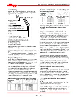
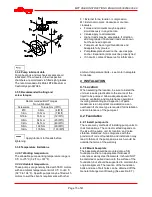
An example of the nameplate used on the MPT 
pump, which is always mounted on the casing, is 
shown below.   


Serial No. 

Equipment No.  

Purchase 

Order 

Model 

Size 

MDP 

Material 

Date 


Summary of Contents for MPT 20

Page 1: ... Pumps USER INSTRUCTIONS INSTALLATION OPERATION MAINTENANCE PCN 85392699 07 09 E These instructions must be read prior to installing operating using and maintaining this equipment ПромХимТех официальный дистрибьютор и сервис партнер www promhimtech ru zakaz promhimtech ru 8 800 250 0154 ...

Page 2: ...15 3 3 5 Recommended bolting and screw torques 15 3 3 6 Temperature limitations 15 4 INSTALLATION 15 4 1 Location 15 4 2 Foundation 15 4 2 1 Install pump units 15 4 2 2 Mount baseplate 15 4 2 3 Install baseplate 16 4 3 Grouting 16 4 3 1 Grouting foundation bolts 16 4 3 2 Grouting baseplate 16 4 3 3 Grouting baseplate prevents movement 16 4 4 Initial alignment 16 4 4 1 Thermal expansion 16 4 4 2 Al...

Page 3: ...l drawings 22 6 6 2 Prepare 22 6 6 3 Bearings 22 6 6 4 Mechanical seal 22 6 6 5 Impeller 22 6 6 6 Suction flange 22 6 6 7 Coverplate wear plate 22 6 6 8 Back pull out assembly case 23 6 6 9 Lubrication 23 6 6 10 Final assembly 23 6 7 Spare Parts 23 6 7 1 Ordering of spares 23 6 7 2 Pump details 23 6 7 3 Genuine parts 23 6 7 4 Recommended spares 23 6 7 5 Storage of spares 24 7 FAULTS CAUSES AND REM...

Page 4: ...re applicable this document incorporates information relevant to these Directives and Approvals To confirm the Approvals applying and if the product is CE marked check the serial number plate markings and the Certification See section 9 Certification 1 3 Disclaimer Information in these User Instructions is believed to be reliable In spite of all the efforts of Flowserve to provide sound and all ne...

Page 5: ...and actions to help prevent injury to personnel and damage to the environment and to equipment For products used in potentially explosive atmospheres section 1 6 4 also applies NEVER DO MAINTENANCE WORK WHEN THE UNIT IS CONNECTED TO POWER Lock out DRAIN THE PUMP AND ISOLATE PIPING BEFORE DISMANTLING THE PUMP The appropriate safety precautions should be taken where the pumped liquids are hazardous ...

Page 6: ...t period can unscrew the impeller which can cause significant damage 1 6 4 Products used in potentially explosive atmospheres Always check that the driver drive coupling assembly and pump equipment are suitably rated and or certified for the classification of the specific atmosphere in which they are installed See section 9 Certification Measures are required to Avoid excess temperature Prevent bu...

Page 7: ...ce temperature permitted Temperature limit of liquid handled depending on material and construction variant check which is lower T6 T5 T4 T3 T2 T1 85 C 185 F 100 C 212 F 135 C 275 F 200 C 392 F 300 C 572 F 450 C 842 F Consult Flowserve Consult Flowserve 110 C 230 F 175 C 347 F 270 C 518 F 350 C 662 F The responsibility for compliance with the specified maximum liquid temperature is with the plant ...

Page 8: ... mechanical seal The pump must only be used to handle liquids for which it has been approved to have the correct corrosion resistance Avoid entrapment of liquid in the pump and associated piping due to closing of suction and discharge valves which could cause dangerous excessive pressures to occur if there is heat input to the liquid This can occur if the pump is stationary or running Bursting of ...

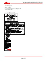
Page 9: ...MPT USER INSTRUCTIONS ENGLISH 85392699 06 09 Page 9 of 41 1 7 Safety Labels 1 7 1 Nameplates For details of nameplate see the Declaration of Conformity and section 3 1 7 2 Warning labels tags ...

Page 10: ...r Consult Flowserve or a noise specialist if assistance is required in combining the values It is recommended that where exposure approaches the prescribed limit then site noise measurements should be made The values are in sound pressure level LpA at 1 m 3 3 ft from the machine for free field conditions over a reflecting plane For estimating sound power level LWA re 1pW then add 14 dBA to the sou...

Page 11: ... Use either a sling or hook through each of the two lifting lugs located on the side of the casing 2 3 1 2 Bearing Housing 3200 Insert an eye hook in the drilled and tapped hole at the top of the bearing housing Use either a sling or hook through the eyebolt 2 3 1 3 Power end Same as bearing housing 2 3 1 4 Bare pump Use either a sling or hook through each of the two lifting lugs located on the si...

Page 12: ...dust etc Warranty for the pumps will normally be for 12 months Extension of this period can only be achieved with the prior agreement of Flowserve and would necessitate inspection prior to putting the pump into service After unpacking protection will be the responsibility of the user Addition of oil to the bearing housing will remove the inhibitor If units are to be idle for extended periods after...

Page 13: ...vel is monitored via the sight glass fitted high on the bearing housing allowing the pump to be shut down in the event of a seal failure indicated by a sudden drop in oil level or product showing in the oil A vent is also fitted at the top of the housing to maintain even atmospheric pressure in the oil chamber The seal housing is easily replaceable if wear from the impeller back sealing vanes beco...

Page 14: ...imits for the flanges are in accordance with the relevant National or International standards unless advised otherwise 3 3 3 Flange loads The permissible flange loading has been listed in the table below Maximum forces kN lbf and Moments kN m lbf ft Pump Size Fx Fy Fz Mx My Mz MODEL 20 293 7 66 023 8 234 3 526 703 6 191 4 43 026 7 151 8 111 967 7 75 9 55 983 8 115 5 85 192 8 MODEL 30 438 9 98 664 ...

Page 15: ...mperature These pumps are generally fitted with TEFC motors with an ambient temperature limit of 0 C to 40 C 32 F to 104 F Specific pumps may be fitted wit h motors to suit the client s requirements with other ambient temperature limits see motor nameplate for details 4 INSTALLATION 4 1 Location When selecting the location be sure to install the unit as close as practicable to the source of the li...

Page 16: ...E TOP OF FOUNDATION ROUGH CONCRETE DO NOT FINISH WITH TROWEL 4 3 3 Grouting baseplate prevents movement Grouting provides solid contact between the pump unit and foundation prevents lateral movement of vibrating equipment and dampens resonant vibrations 4 4 Initial alignment 4 4 1 Thermal expansion The pump and motor will normally have to be aligned at ambient temperature and should be corrected t...

Page 17: ...nd directly on the suction branch A long radius suction bend may be used as long as the bend is perpendicular to the shaft center line of the unit Do not install elbows at an angle other than perpendicular to the shaft axis Elbows parallel to the shaft axis will cause uneven flow into the impeller eyes Inlet strainers when used should have a net free area of at least three times the inlet pipe are...

Page 18: ...rox 350 ml 11 83 fl oz of oil Check oil level at the sight glasses provided before putting into service 5 1 1 2 Driver bearing Driver bearing lubrication should be in accordance with the driver manufacturer s instruction manual 5 1 1 3 Coupling lubrication Coupling lubrication if required should be in accordance with the coupling manufacturer s instruction manual 5 1 2 Pre operation check list Pre...

Page 19: ...0 seconds 5 2 8 Check the pump unit for vibration or overheating If the vibration and or temperature are excessive STOP the pump Refer to Faults Causes and Remedies chart Section 7 for fault diagnosis 5 3 Running Vent the pump to enable all trapped air to escape taking due care with hot or hazardous liquids Under normal operating conditions after the pump has been fully primed and vented it will b...

Page 20: ...etween oil changes are 4000 operating hours or a 12 month period The characteristics of the installation and severity of service will determine the frequency of lubrication change See Section 3 3 4 Pump lubricant data Any sudden change in oil level should be investigated without delay A rise in bearing housing oil level together with a drop in the seal chamber oil level indicates a secondary seal ...

Page 21: ...sing and cover Discard gasket and lip seal and replace with new parts on assembly Press or drive shaft complete with bearings from bearing housing in the direction of the coupling end of the shaft Remove the drive end bearing circlip 6544 from the shaft Note that the circlip is fitted to all size pumps except the MODEL 80 Remove the bearings from the shaft using a suitable bearing puller applying ...

Page 22: ...use a flame on the bearings Fit the circlip 6544 to the shaft at the outboard bearing 3041 Note that a circlip is fitted on all pump sizes except the MODEL 80 Support shaft bearing assembly on clean vee blocks under the bearings and check shaft runout at coupling end and mechanical seal area Runout is not to exceed 0 05 mm 0 002 in TIR Push shaft bearing assembly into bearing housing from drive en...

Page 23: ...for leaks Now that seals are lubricated check element for free rotation 6 6 10 Final assembly Refit coupling and connect driver Check driver alignment Refit guards Refit suction and discharge piping with new gaskets Check all fasteners and plugs for tightness 6 7 Spare Parts 6 7 1 Ordering of spares Flowserve keeps records of all pumps that have been supplied When ordering spares the following inf...

Page 24: ...MPT USER INSTRUCTIONS ENGLISH 85392699 06 09 24 of 41 Page left intentionally blank ...

Page 25: ...l sleeve joints casing joint or pipe lugs Check airtight assembly then joints and gaskets Foot valve too small Investigate replacing the foot valve Foot valve partially clogged Clean foot valve Inlet of suction pipe insufficiently submerged Check cut out system design Total head of system higher than differential head of pump Check discharge head and head losses in discharge pipe at the valve sett...

Page 26: ...ignment Check misalignment and correct if necessary If alignment satisfactory check bearings for excessive wear Impeller out of balance resulting in vibration Check and consult Flowserve Abrasive solids in liquid pumped Check and consult Flowserve Mechanical seal was run dry Check mechanical seal condition and source of dry running and repair Internal misalignment due to improper repairs causing i...

Page 27: ...MPT USER INSTRUCTIONS ENGLISH 85392699 06 09 27 of 41 8 PARTS LIST AND DRAWINGS 8 1 Sectional Arrangement and Parts List Drawings MODEL 20 ...

Page 28: ...11EM222 VITON 95022232 1 4610 2 O RING COVER PLATE CASING 1 20A11CM437 Buna N 95087243 1 4610 1 O RING BEARING HSG SEAL HSG 1 20A11CM244 Buna N 95086666 1 4610 0 O RING CASING BEARING HSG 1 20A11CM360 Buna N 95277265 1 4590 2 GASKET END COVER 1 2584A020MPTA001 NTL SYN 75530964 1 4590 1 GASKET FLANGE SUCTION 1 2586A020MPTA001 NTL SYN 75516666 1 4590 0 GASKET DISCHARGE 1 32A11X6 NTL SYN 60669868 1 4...

Page 29: ...MPT USER INSTRUCTIONS ENGLISH 85392699 06 09 29 of 41 8 2 Sectional Arrangement and Parts List Drawings MODEL 30 ...

Page 30: ...VER PLATE CASING 1 20A11CM447 Buna N 95017919 1 4610 1 O RING BEARING HSG SEAL HSG 1 20A11CM260 Buna N 95086898 1 4610 0 O RING CASING BEARING HSG 1 20A11CM446 Buna N 95017901 1 4590 2 GASKET END COVER 1 2586A030MPTA001 NTL SYN 75530345 1 4590 1 GASKET FLANGE SUCTION 1 2586A030MPTA001 NTL SYN 75516674 1 4590 0 GASKET DISCHARGE 1 32A11X8 NTL SYN 60669876 1 4300 LIP SEAL BEARING COVER 1 2796A175DIAB...

Page 31: ...MPT USER INSTRUCTIONS ENGLISH 85392699 06 09 31 of 41 8 3 Sectional Arrangement and Parts List Drawings MODEL 40 ...

Page 32: ...75530345 1 4590 1 GASKET FLANGE SUCTION 1 2586A040MPTA001 NTL SYN 75516682 1 4590 0 GASKET DISCHARGE 1 32A11X10 NTL SYN 60669884 1 4300 LIP SEAL BEARING COVER 1 2796A175DIAB001 NITRILE 75554055 2 4200 MECHANICAL SEAL 1 1802A150MPTA002 BX C F X JF 75555318 4011 SEAL HOUSING 1 2632A040MPTA001 C I 75517383 3858 SIGHT GLASS 3 4260A000MPTA001 POLYMIDE 75553578 3854 AIR VENT 2 0319A00VENTB003 STEEL 6061...

Page 33: ...MPT USER INSTRUCTIONS ENGLISH 85392699 06 09 33 of 41 8 4 Sectional Arrangement and Parts List Drawings MODEL 60 ...

Page 34: ...ER PLATE CASING 1 20A11CM454 Buna N 95018354 1 4610 1 O RING BEARING HSG SEAL HSG 1 20A11CM260 Buna N 95086898 1 4610 0 O RING CASING BEARING HOUSING 1 20A11CM454 Buna N 95018354 1 4590 2 GASKET END COVER 1 2584A030MPTA001 NTL SYN 75530345 1 4590 1 GASKET FLANGE SUCTION 1 2586A060MPTA001 NTL SYN 75516690 1 4590 0 GASKET DISCHARGE 1 32A11X12 NTL SYN 84636000 1 4300 LIP SEAL BEARING COVER 1 2796A175...

Page 35: ...MPT USER INSTRUCTIONS ENGLISH 85392699 06 09 35 of 41 8 5 Sectional Arrangement and Parts List Drawings MODEL 80 ...

Page 36: ... O RING BEARING HSG SEAL HSG 1 20A11CM268 Buna N 95097937 1 4610 0 O RING CASING BEARING HOUSING 1 20A11CM458 Buna N 95017968 1 4590 2 GASKET END COVER 1 2584A080MPTA001 NTL SYN 75530352 1 4590 1 GASKET FLANGE SUCTION 1 2586A080MPTA001 NTL SYN 75516708 1 4590 0 GASKET DISCHARGE 1 32A11X13 NTL SYN 60669892 1 4300 LIP SEAL BEARING COVER 1 2796A200DIAA001 NITRILE 60609872 2 4200 MECHANICAL SEAL 1 180...

Page 37: ...e Examples are certificates for CE marking ATEX marking etc If required copies of other certificates sent separately to the Purchaser should be obtained from the Purchaser for retention with these User Instructions 10 OTHER RELEVANT DOCUMENTATION AND MANUALS 10 1 Supplementary Instruction Manuals See also the supplementary instruction manuals supplied with this manual e g for electric motors contr...

Page 38: ...MPT USER INSTRUCTIONS ENGLISH 85392699 06 09 38 of 41 NOTES ...

Page 39: ...MPT USER INSTRUCTIONS ENGLISH 85392699 06 09 39 of 41 NOTES ...

Page 40: ...MPT USER INSTRUCTIONS ENGLISH 85392699 06 09 40 of 41 NOTES ...

Page 41: ...orporation Pump Division 6840 Wynnwood Lane Houston Texas 77008 USA Telephone 1 713 803 4434 Fax 1 713 803 4497 Asia Pacific Flowserve Pte Ltd Pump Division 200 Pandan Loop 06 03 04 Pantech 21 Singapore 128388 Telephone 65 775 3003 Fax 65 779 4607 Visit our web site at www flowserve com Your Flowserve factory contact Flowserve Pump Division 3900 Cook Boulevard Chesapeake VA 23323 1626 USA Telephon...

Reviews: