23
8.1 Grounding screw
The grounding screw, located inside the
positioner cover, should be used to prov-
ide the unit with an adequate and reliable
earth ground reference. This ground
should be tied to the same ground as the
electrical conduit. Additionally, the
electrical conduit should be earth
grounded at both ends of its run. The
grounded scrrew must not be used to
termingate signal shield wires.
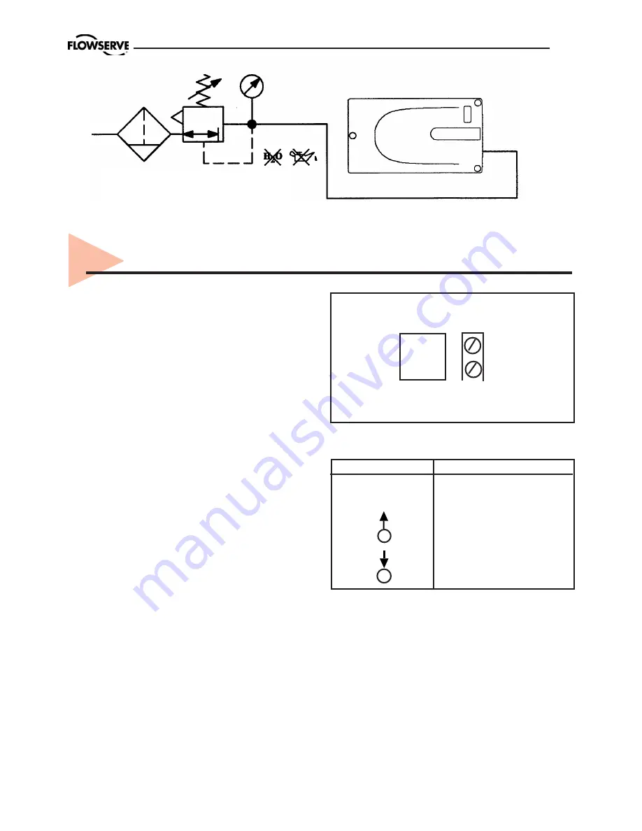
Figure 8. Connections
Electrical connections:
signal cable
with cable passage (1/2” NPT, or M20 x
1,5) to terminals 2 x 2,5 mm.
Input signal:
4 – 20 mA
NOTE:
Observe the minimum
requirements of voltage and equivalent
electrical load:
8 VDC at 20 mA
The performance is ensured only for a
minimum input current of 3,6 mA.
For wiring, the following notes should be
observed:
NOTE:
The input loop current signal to
the
PMV D20
should be in shielded cable.
Shields must be tied to a ground at only
one end of the cable to provide a place
for environmental electrical noise to be
removed from the cable. In general,
shield wire should be connected at the
source. (Figure 8).
Connect the 4-20 mA current source to
ter1 and -2, see connection ta-
ble.
8. Wiring and grounding guidelines
Connection Description
+1
Input +4-20 mA
–2
Input –4-20 mA
Pneumatic output
signal (outlet)
Air supply
+ –
4 - 20 mA
IN
1 2
ISO 8573 2.2.2
ISA 7.0.01.-1996 Class 2
2 - 6 bar
30 - 90 Psi
5
µ
Summary of Contents for PMV D20
Page 1: ...Installation Operation Maintenance PMV D20 Digital Positioner ...
Page 11: ...11 4 5 Control Drawing ...
Page 12: ...12 4 6 Certificates ...
Page 13: ...13 ...
Page 14: ...14 ...
Page 15: ...15 ...
Page 32: ...32 12 Spare parts 12 11 16 15 19 18 17 1 21 2 14 3 5 8 7 9 4 ...


