USER INSTRUCTIONS POLYCHEM GRP ENGLISH 71569132 12-04A
Page 39 of 52
flowserve.com
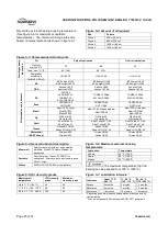
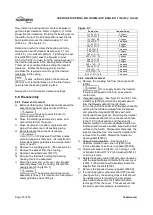
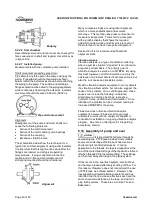
Diameter/tolerance, outside diameter
In order to ensure proper fit between bearings and
the bearing housing, verify that the OD on both the IB
and OB bearings are consistently within the
minimum/maximum values shown in figure 6-21. A
micrometer should be used to check these outside
diameter (OD) dimensions on the bearings.
6.9.4.3 Impeller balancing
Shaft whip is deflection where the centerline of the
impeller is moving around the true axis of the pump.
It is not caused by hydraulic force but rather by an
imbalance with the rotating element. Shaft whip is
very hard on the mechanical seal because the faces
must flex with each revolution in order to maintain
contact. To minimize shaft whip it is imperative that
the impeller is balanced. All impellers manufactured
by Flowserve are balanced after they are trimmed. If
for any reason, a customer trims an impeller, it must
be re-balanced. See note 1 under figure 6-19
regarding acceptance criteria.
6.9.4.4 Bearing housing and carrier
Prior to installing the shaft into the bearing housing,
check the following parameters.
Diameter/tolerance, at bearing surface
In order to ensure proper fit between the bearing
housing/carrier and the bearings, verify that the ID of
both the IB and OB bearing surfaces are consistently
within the minimum/maximum values shown in figure
6-21. An inside caliper should be used to check
these ID dimensions in the bearing housing.
6.9.4.5 Power end
Assembled bearing housing, carrier, bearings, and
shaft.
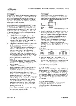
Shaft and shaft sleeve run-out
Shaft run-out is the amount t
he shaft is “out of true”
when rotated in the pump. It is measured by attaching a
dial indicator to a stationary part of the pump so that its
contact point indicates the radial movement of the shaft
surface as the shaft is rotated slowly. If a shaft sleeve is
used then shaft sleeve run-out must be checked. It is
analogous to shaft run-out. Measurement of shaft run-
out/shaft sleeve run-out will disclose any out of
roundness of the shaft, any eccentricity between the
shaft and the sleeve, any permanent bend in the shaft,
and or any eccentricity in the way the shaft or bearings
are mounted in the bearing housing.
Shaft run-out can shorten the life of the bearings and
the mechanical seal.
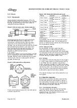
Figure 6-21
Group 1
Group 2
Group 3
OB
bearing/
carrier
mm (in.)
Bearing
71.999/71.986
(2.8346/2.8341)
110.000/109.985
(4.3307/4.3301)
150.000/149.979
(5.9055/5.9047)
Carrier
71.999/72.017
(2.8346/2.8353)
110.007/110.022
(4.3310/4.3316)
150.002/150.030
(5.9056/5.9067)
Fit
0.031L/0.000L
(0.0012L/0.0000L)
0.037L/0.007L
(0.0015/0.0003L)
0.051L/0.002L
(0.0020L/0.0001L)
IB
bearing/
housing
mm (in.)
Bearing
71.999/71.986
(2.8346/2.8341)
110.000/109.985
(4.3307/4.3301)
150.000/149.979
(5.9055/5.9047)
Housing
71.999/72.017
(2.8346/2.8353)
110.007/110.022
(4.3310/4.3316)
150.007/150.025
(5.9058/5.9065)
Fit
0.031L/0.000L
(0.0012L/0.0000L)
0.037L/0.007L
(0.0015L/0.0003L)
0.046L/0.007L
(0.0018L/0.0003L)
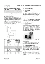
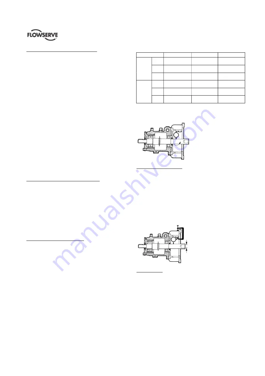
The following diagram shows how to measure shaft/shaft
sleeve run-out. Note that both ends need to be checked.
The run-out should be 0.025 mm (0.001 in.) FIM or less.
Runout
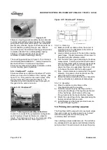
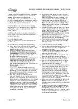
Radial deflection - static
Radial movement of the shaft can be caused by a loose
fit between the shaft and the bearing and/or the bearing
and the housing. This movement is measured by
attempting to displace the shaft vertically by applying an
upward force of approximately 4.5 kg (10 lb) to the
impeller end of the shaft. While applying this force, the
movement of an indicator is observed as shown in the
following diagram. The movement should be checked
at a point as near as possible to the location of the seal
faces. A movement of more than 0.05 mm (0.002 in.) is
not acceptable.
Deflection
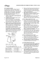
Shaft endplay
The maximum amount of axial shaft movement, or
endplay, on a Durco pump should be 0.03 mm
(0.001 in.) and is measured as shown below.
Observe indicator movement while tapping the shaft
from each end in turn with a soft mallet. Shaft
endplay can cause several problems. It can cause
fretting or wear at the point of contact between the
shaft and the secondary sealing element. It can also
cause seal overloading or underloading and possibly
chipping of the seal faces. It can also cause the
faces to separate if significant axial vibration occurs.

