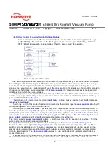
background image

54 


Flowserve US Inc. 


SIHI

dry

dry

dry

dry

    Standard 

Standard 

Standard 

Standard M Series    

Dry Running Vacuum Pump


Issue Date:             November 21, 2016         Copyright:  

FLOWSERVE SIHI Pumps                                     Rev 1 


9  Start Up. Operation & Shut Down of the SIHIdry


Vacuum Pump


9.1  Preparation


The pump system must be installed according to the instructions in chapter 8 Installation of The 
SIHIdry Vacuum Pump 


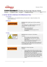
9.2  Personal


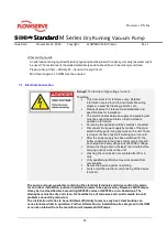
Warning!  Risk of injuries may occur due to untrained 
personal. 


Unauthorized and / or untrained person may get injured 
during installation preparation and work 


Therefore: 

Only authorized personal. 

Use original spare parts. 

Use only the accessories approved by the 
manufacturer. 


9.3  Safety


Warning!  Risk of burning due to hot surfaces. 

Therefore: 

Before starting any activity, ensure that all 
components are cooled down to the ambient 
temperature or 

Wear protective work clothing and safety gloves 
when working near hot components. 


Surfaces of inlet, outlet pipes and pump casing may be hot. 
The operating company of the device must ensure that the 
corresponding sign is affixed. 


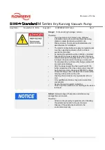
Warning!  Pre-Check Pump Safety. 

Therefore: 

Check the filling height of the cooling water circuit. 

If explosive, toxic, hot or corrosive gases and vapors 
are handled it must be ensured that personnel and 
the environment are not endangered. 

The electrical connection for the pair of motors (pay 
attention to the correct direction of rotation) must be 
carried out in such a way that the vacuum pump can 
only be switched on after release by the Purge 
Control. 


Summary of Contents for SIHI dry Standard H Series

Page 1: ...andard M Series Dry Running Vacuum Pump Issue Date November 21 2016 Copyright FLOWSERVE SIHI Pumps Rev 1 Dry Running Vacuum Pump SIHIdry For The Chemical Pharmaceutical Industry Instruction Operation Manual FLOWSERVE SIHI Pumps Inc 225 Speedvale Ave W Guelph ON N1H 6L8 ...

Page 2: ... 1 8 Position Of Nameplate 12 1 9 Copyright Protection 12 2 Safety 13 2 1 Intended Use 13 2 2 Foreseeable Misuse 13 2 3 Normal Source Of Danger 13 2 3 1 High Voltage Current 13 2 3 2 Gases Vapors 14 2 3 3 Hot Surfaces 14 2 3 4 Accumulated Liquid 14 2 3 5 Dirt And Scattered Objects 14 2 3 6 Noise 14 2 3 7 Suspended Loads 15 2 3 8 Sharp edged and pointed corners 15 2 3 9 Chemicals Medium 15 2 3 10 U...

Page 3: ...Purged Enclosure acc NFPA496 28 3 6 1 Safety Pressure Switch Purge Type NFPA 496 Completed 29 3 6 2 Settings Purge Gas Pressure 30 3 7 Technical Data Utility Requirements 31 3 8 Utility Connections and Supply 31 3 9 Performance Range for SIHIdry M Version 32 4 Transportation of SIHIdry Vacuum Pump 33 4 1 Safety 33 4 1 1 Suspended Loads 33 4 1 2 Swiveling Transport Unit 33 4 2 Off Center Center of ...

Page 4: ...m Pump 52 8 1 Preparation 52 8 2 Safety 52 8 3 Special Tools 52 8 4 Permitted Environmental Condition 52 8 5 Base Foundation 52 8 6 Space Requirements 52 8 7 Check List before Installation 52 8 8 Installation of SIHIdry Vacuum Pump into Pipework 53 8 9 Electrical Connection 53 8 10 Final Checklist 53 8 11 Vacuum Pressure Test 53 9 Start Up Operation Shut Down of the SIHIdry Vacuum Pump 54 9 1 Prep...

Page 5: ...6 10 5 Disassembly Assembly 66 10 5 1 Disassembly 67 10 5 1 1 Preparation 67 10 5 1 2 Removal of the Suction Cover 67 10 5 1 3 Removal of the Pump Chamber Housing 68 10 5 1 4 Removal of the Discharge Branch 68 10 5 1 5 Disassembly of Cooling Unit 69 10 5 2 Assembly 70 10 5 2 1 Assembling the Discharge Orifices 71 10 5 2 2 Assembling the Cooling Unit 72 10 5 2 3 Assembling the Spindle Pump Housing ...

Page 6: ...ng Vacuum Pump Issue Date November 21 2016 Copyright FLOWSERVE SIHI Pumps Rev 1 List of Table Table 1 Technical Data Utility Requirements 31 Table 2 Utility Connection and Supply for the SIHIdry M Version 31 Table 3 Vital Status Description 4 20mA Feedback Signal 50 Table 4 Spare Parts List 75 ...

Page 7: ...Connection 39 Figure 15 Flange Force Torque Cooling Connection 39 Figure 16 Electronic Housing 46 Figure 17 STE12 Synchronization Board 47 Figure 18 Example Electrical Connection Safety Chain 51 Figure 19 Operating Indicators 56 Figure 20 Expo Purge Gas Control Unit 58 Figure 21 Operation Flow Chart 59 Figure 22 Suction Sieve Purge Gas Unit 63 Figure 23 Bearing Arrangement 63 Figure 24 Overview of...

Page 8: ...HI Pumps Rev 1 1 General Information 1 1 SIHI Pumps Contacts 1 1 1 Canada Guelph ON FLOWSERVE Canada Corp 225 Speedvale Rd W Guelph ON Canada N1H 6L8 Tel 519 824 4600 1 1 2 USA Pasadena TX FLOWSERVE US Inc 5757 Genoa Red Bluff Rd Pasadena TX 77507 Tel 281 991 3100 1 1 3 Germany Itzehoe FLOWSERVE SIHI Pumps Lindenstrasse 170 25524 Itzehoe Tel 49 0 4821 771 01 ...

Page 9: ...ely Furthermore locally applicable accident prevention regulations and general safety regulations shall be applicable for the area of application of the device Figures in this manual are meant only for fundamental understanding and may vary from the actual model In addition to this manual manuals of installed components listed in the annex shall be applicable 1 3 Explanation of Safety Instructions...

Page 10: ... regulations prevailing at the time of concluding the agreement shall be applicable 1 6 Guarantee Guarantee conditions are included in sales documents 1 7 Declaration of Conformity of North American Standards The Dry Running Vacuum Pump SIHI dry and or System are designed and manufactured to meet latest edition of the following standards or codes National Electrical Manufacturers Association NEMA ...

Page 11: ... have three 3x name type plates Pump Head Vacuum Pump Vacuum Pump System 1 9 Copyright Protection This manual has been protected by the copyright law This manual or parts may not be transferred to any third party duplicated in any form and using any method and its contents may not be used and or notified to external entities without a prior written consent of the manufacturer Violations shall be s...

Page 12: ... unintended use 2 2 Foreseeable Misuse WARNING Risk due to misuse Any usage that goes beyond and or deviates from the intended use may lead to hazardous situations Under specified process conditions hazardous mixtures may not be fed such as Combustible substances Explosive substances Toxic substances Radioactive substances Corrosive gases or vapors 2 3 Normal Source of Danger Remaining risks deriv...

Page 13: ...nts are cooled down to the ambient temperature Wear protective work clothing and safety gloves when working near hot components Surfaces of inlet outlet pipes and pump casing may be hot The operating company of the device must ensure that the corresponding sign is affixed 2 3 4 Accumulated Liquid Warning Risk of slipping due to accumulated liquid Therefore Wear protection shoes Remove leaked liqui...

Page 14: ...ads are attached horizontally 2 3 8 Sharp edged and pointed corners Caution Risk of injuries due to sharp edges and pointed corners Sharp edges and pointed corners may lead to abrasions and cuts on the skin Therefore Be careful when working near sharp edges and pointed corners Wear safety gloves in case of any doubt 2 3 9 Chemicals Medium Danger Risk of poisoning irritations to the skin and seriou...

Page 15: ...e original spare parts Use only the accessories approved by the manufacturer 2 3 11 Hydrostatic Pressure Test of the Piping System Notice The device may get damaged if the hydrostatic pressure test of the piping system is not conducted properly Therefore When conducting the hydrostatic pressure test of the piping system shut off the inlet and outlet pipes of the device 2 3 12 Substances Harmful to...

Page 16: ...llation site of the device It must include these in the form of operating instructions for the device During the entire service life of the device the operating company must check whether the operating instructions given by it comply with the current version of regulations and if required modify these instructions The operating company must define and control the responsibilities for installation ...

Page 17: ...ions applicable at the installation location when selecting the personnel The following qualifications for different areas of activities are specified in the operating manual Manufacturer Flowserve SIHI Service Personnel Flowserve SIHI Pumps Service Technician appointed by Flowserve SIHI Pumps Operating Company a Trained Personnel The person has been trained on the tasks entrusted to him her and p...

Page 18: ... have suitable physical mental and behavioral characteristics to drive industrial trucks having a driver s seat or driver s control panel or cranes Furthermore the stacker or crane driver must be trained specially to drive industrial trucks having a driver s seat or driver s control panel or cranes The stacker or crane driver must prove his her abilities of driving industrial trucks having a drive...

Page 19: ... Inc SIHIdry dry dry dry Standard Standard Standard Standard M Series Dry Running Vacuum Pump Issue Date November 21 2016 Copyright FLOWSERVE SIHI Pumps Rev 1 2 6 Safety Signs Figure 3 Safety Sign SIHIdry Vacuum Pump ...

Page 20: ...work clothing includes well fitted clothes with low tensile strength short sleeves and without protruding parts Protective Ear Protectors Ear protectors protect ears from loud noise Protective Safety Glasses Protective goggles protect eyes from flying parts and liquid sprays Protective Helmet A protective helmet provides protection from falling objects and injuries due to impacts Protective Shoes ...

Page 21: ... suction port with metal contact inside the seal The SIHIdry system should not be operated without the suction sieve The suction sieve insert is included in the scope of supply Figure 4 Strainer Insert Sieve The SIHIdry system should not be operated without the suction sieve 2 8 2 Suction Check Valve Inlet Vacuum Pump Optional Suction Check Valve The suction check valve prevents in an event on the...

Page 22: ...mponents from moving or turning as quickly as possible and switch off the power supply Proceed as follows in case of an emergency 1 Stop the device immediately using the Machine stop 2 If there is no risk to your health rescue the persons from the danger zone 3 If required initiate first aid measures 4 Contact the fire brigade and or rescue service 5 Inform the on site in charge 6 Switch off the d...

Page 23: ...ed out and the pump comes to a standstill in a controlled manner A separate motor and an angle sensor system H are provided for every shaft Motors being an integral component of the pump abrasive shaft seals are not required and the pump is outwardly air tight Lead screws C are rotated in reverse directions without coming in contact with each other or with the casing walls D Gas from the top inlet...

Page 24: ... solely rely on the electronic synchronization Consequently no precautions are necessary when stopping the pump and a special safety analysis for fault free operation of the hardware and software is not needed The SIHIdry has been developed for use in a hazardous area The electrical system has been designed for easy connection to the power supply The unit requires only 460V 3phase supply and 24V D...

Page 25: ...g removes the heat of compression from the cooling jacket filled with a coolant factory pre filled with a mixture of water glycol refer to data sheet Due to indirect cooling the spindle pump casing is maintained at a high temperature to avoid condensation in the pump Likewise the calcification of cooling water channels is ruled out to a great extent due to the high flow velocities The coolant supp...

Page 26: ...driving compartment against the discharge compartment to effectively ensure that the feeding medium does not enter the driving compartment 3 5 Functional Description Labyrinth Piston Ring Purge Figure 10 Piston Ring Purge In conjunction with the Labyrinth seal the piston rings are in addition purged with about 10SLM 2 5CFM to prevent condensation of condensable This dilution effect helps to avoid ...

Page 27: ...otor compartment and electronic casing is prevented by maintaining the inflammation protection gas nitrogen at an excess pressure in these compartments A differential pressure switch is installed to monitor the pressure difference of the discharge of the pump chamber and the electrical casing If the discharge pressure becomes greater than or equal to the electrical casing pressure the SIHIdry syst...

Page 28: ...FPA 496 Completed A safety pressure switch installed within Ex protection Method Device Expo Purge Gas System and is calibrated to min 2 9 PSIG 200mbarg 3 6 2 Settings Purge Gas Pressure The min purge pressure Leakage Compensation Regulator is calibrated to 3 6 PSIG Note Calibration of this Leakage Compensation Regulator needs to be checked every six 6 months for correct pressure 3 6 PSIG and shal...

Page 29: ...as a differential safety pressure switch can be installed to measure positive pressure between Electronic Housing and discharge of the vacuum pump In an event of discharge pressure is rising up against 0 5 PSIG main power will be cut off To avoid explosive or hazard process gas will enter the electronic motor housing a discharge mounted isolation valve is recommended which will close and isolate a...

Page 30: ... 63 57 63 57 63 Max Sound Level A dB A 54 54 54 54 Weight incl Basic Accessories G lbs 750 750 750 760 Table 1 Technical Data Utility Requirements 3 8 Utility Connections and Supply for the SIHIdry M Version Technical Data Overview For Model SIHIdry M100 M160 M250 M400 End Pressure Inlet Flange pend torr 0 5 0 3 0 01 0 001 Max Process Gas Temperature Inlet Flange tMaxI F 212 212 212 212 Min Proces...

Page 31: ...ry Running Vacuum Pump Issue Date November 21 2016 Copyright FLOWSERVE SIHI Pumps Rev 1 3 9 PERFORMANCE RANGE for the SIHIdry M Version Every operating point below the maximum characteristic curve displayed below is possible by the set point of speed Figure 12 Capacity Curve for M Series ...

Page 32: ...ansport unit The transport unit may swivel when transporting with the crane This may cause serious injuries and considerable material damage Therefore Ensure that there are no persons objects or obstacles located in the swiveling range of the transport unit during transport 4 2 Off Centre Centre Of Gravity Warning Risk of injuries due to falling or tilting transport units Transport units may have ...

Page 33: ...ically if it is kept on inclined surfaces Therefore Transport the device only on horizontal surfaces It is possible that components parts may be delivered disassembled for transport reasons Necessary assembly components are included in the scope of supply Take care that all items are received For the transport of the pump set the manufacturer can provide a transport cage In this case the pump set ...

Page 34: ... delivery or accept it conditionally Specify the extent of damage on transport documents or on the receipt and or delivery note of the transporter Lodge a complaint for every defect as soon as it is detected You can assert the damage claims only within the applicable complaint periods 5 1 Symbols on the Package Protect the transport unit from humidity and keep in a dry place The transport unit is ...

Page 35: ...rrosive mediums Protect from solar radiation Avoid mechanical shocks Storage temperature 4 F to 104 F 0 C to 40 C Relative humidity 20 90 Note If it s stored for more than 3 months check the condition of all parts and the packing at regular intervals If required ask the SIHI service technician to replenish or replace the conservation aids 6 4 Preservation The connections of the unit are preserved ...

Page 36: ...on The vacuum system is designed in accordance to electromagnetic compatibility to be used in industrial surrounding 2 nd Environment Category C3 Caution Unwanted installation condition must be avoided The presence of corrosive and aggressive media should be as less as possible to hamper the service life of the system The place of installation must be adequately ventilated Therefore Avoid direct r...

Page 37: ...he vacuum system as per specifications in the Forces and Moments Figure 14 Lay the pipelines in such a way that thermal expansions do not cause undue forces and moments on connections in joint of pipelines Use compensators if required Avoid sudden changes in pipe diameters and directions Tapered pieces shall be used to change pipe diameters Prevent surges of water or other liquid from getting into...

Page 38: ...ection Permissible forces on branches and permissible moments for cooling water inlet and outlet flange of the pump If different point forces are existing at the same time the components of the resultants of these forces may not exceed the permissible values of each direction of force If these requirements are not to meet tightness and durability cannot be warranted Option SIHIdry Base Frame allow...

Page 39: ...te does not flood into the pump The SIHIdry system can handle a low continuous liquid flow only if it is assured that the liquid does not react with materials The condensate cannot be fed if other vacuum pumps are integrated into this system e g lobular pump Avoid Liquid Particle Carry Over Install a liquid or condensate separator in the suction pipe for large liquid or condensate volumes and lay ...

Page 40: ...ubstances that may deposit or are sticky are fed along with the fluid Deposited substances can be flushed with a suitable solvent if required Avoid Pockets Pipelines must be laid in compliance with at least the nominal sizes of connections Avoid abrupt cross sections and changes in direction Adjust different nominal sizes with the help of concentric adapters Keep the number of detachable connectio...

Page 41: ...ide non return valve if possible without spring load 7 2 3 Discharge Pipe Outlet of Vacuum Pump Attenuators or other sound reducing devices must be provided if the feed is against atmospheric pressure The gas outlet should not be closed or covered otherwise cooling of the gas flow is affected and the temperature range cannot be maintained Undue compression pressure may develop in addition to this ...

Page 42: ...wer level and the accumulating condensate drains off without any obstruction Otherwise the accumulated liquid may build up an undue counter pressure or a backflow of the condensate may corrode components of the pump Condensate Discharge If any possibility of condensable occurs ensure that the condensable can be drained all the time without any obstruction Otherwise the accumulated liquid may build...

Page 43: ... pH 6 7 For general information we refer to DIN 50930 Corrosion on metal materials by water particularly part 2 4 and 5 DECHEMA material chart Chemical resistance of the materials Documents of the manufacturer of the material Specialized literature e g Heat exchanger cleaning systems Method for avoiding and elimination of layers and pollutions ISBN 3 934736 02 5 Solids Cooling water which is free ...

Page 44: ... switch before performing any work on the unit There is danger of shock hazard if working on a live unit After the power supply has been switched off the buffer capacitors in the drive control circuit may still be charged and carry dangerous 800VDC voltage Allow a discharge time of at least one minute before carrying out any work on the unit Opening the commission cover plate after 20 min only Onl...

Page 45: ... TB 3 TB PE Control 1 Power Sterling Electronic STE10 ONLY SIHI dry Voltage Current Terminal M100 M160 M250 M400 7 3 1 Main Power and Control Voltage Connection M Series The connected loads refer to the maximum possible electric power data whereby the fuses and cables must be suitable for these load values The actual consumption values depend on the application and the process The valid design and...

Page 46: ...ogue control signals It can also be connected to a local control panel optional Optional Control SIHI Control SABO The behavior of the SIHI dry is determined by a superior control system making available digital and analogue control signals The theoretical value can be set or fixed programmed by means of the optional control panel analogue interface or by digital interface Wireless connection is o...

Page 47: ... Control Remote Control or and CAN Bus Digital inputs have to be maintained Fix speed or speed control via 4 20mA input 4 20mA output Vital status condition of the pump 4 20mA output rotational speed signal Internal service data log DI DO 7 12 for less sensors and actuators 5 for push button signals to customer AI 1 speed set point from customer 1 pressure sensor no analogue temperature sensors AO...

Page 48: ...3 20 Vacuum Mode active Vacuum Mode not active static 11 Cleaning Mode Output X1 3 21 X1 3 22 Cleaning Mode active Cleaning Mode not active static 12 Shut Down Output X1 3 23 X1 3 24 Shut Down active Shut Down not active pulse 13 Set Point Rotational Speed Input X1 3 27 X1 3 28 3 6mA Fault 4mA 0RPM 20mA max speed variable 14 Actual Value Rotational Speed Output X1 3 29 X1 3 30 4mA 0 RPM 20mA max s...

Page 49: ...of the vacuum system Local HMI Operation locally via push buttons for start stop set value Info about parameters from Sabo in Ex d box Optionally Classic I O with additional module Customer Terminal Trim Description DI DO 12 12 for sensors and actuators 8 for push button signals to customer AI 4 temperature sensors PT100 PT1000 4 pressure sensors 4 20 mA AO 4 usually not used Customer Interface CA...

Page 50: ...ard M Series Dry Running Vacuum Pump Issue Date November 21 2016 Copyright FLOWSERVE SIHI Pumps Rev 1 7 3 4 Safety Chain Connection of Pressure Switch Expo Purge Gas Control Unit AC D1 Application Module SIHI Control SABO Figure 18 Example Electrical Connection Safety Chain ...

Page 51: ...ves in the suction or discharge lines are closed Observe and follow local safety regulations codes 8 3 Special Tools During installation no special tools are required 8 4 Permitted Environmental Condition Read the instructions in chapter 7 Planning Installation and the information stated on the data sheet 8 5 Base Foundation The pump unit is fitted with vibration damping feet and must be installed...

Page 52: ...on the vacuum side will reduce suction capacity performance 8 9 Electrical Connection Provide cables with adequate protection local regulations and safety codes must be applied to avoid any danger of mechanical damage When laying outdoors use weather resistant cables 8 10 Final Checklist The following final checks must be carried out 1 Check the pump set is leak tight 2 Check the supply of sealing...

Page 53: ...urer 9 3 Safety Warning Risk of burning due to hot surfaces Therefore Before starting any activity ensure that all components are cooled down to the ambient temperature or Wear protective work clothing and safety gloves when working near hot components Surfaces of inlet outlet pipes and pump casing may be hot The operating company of the device must ensure that the corresponding sign is affixed Wa...

Page 54: ...efore performing any work on the unit There is danger of electrocution if working on a live unit Terminals which are still live after being switched off are marked accordingly After the power supply has been switched off the buffer capacitors in the drive control circuit may still be charged and carry dangerous 800VDC voltage Allow a discharge time of at least one minute before carrying out any wo...

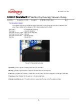
Page 55: ...y stopping Two Green Vacuum Operation One Green One Yellow Start up rotor diagnosis Two Green One Yellow Warning One Green One Red Failure Stopping One Red Failure Stop Figure 19 Operating Indicators Operation green Signals a rotating pump ready for operation Warning yellow Signals trouble or indicates the state of the rotor diagnosis Failure red Signals that a failure or defect has occurred the p...

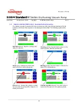
Page 56: ...ignals can be displayed and identified The following signals will be made Operation green Signals a rotating pump ready for operation Cleaning yellow Signals that the pump is in the cleaning phase Rotates with 200rpm Status grey Indicates the state of the electronic drive condition diagnosis Warning yellow Signals trouble or indicates the state of the rotor diagnosis Failure red Signals that a fai...

Page 57: ... 10 min and is indicated with a green display light to the right 1 on the purge gas module After successful completion of the flushing process the contact Pressure Switch in the purge gas module and the corresponding component of the safety chain in the supply are closed This status is indicated by the green display light to the left 2 on the purge gas module Figure 20 Expo Purge Gas Control Unit ...

Page 58: ... makes possible to set 2 different speeds stand by and warm up The change from to this mode of operation is initiated by the control signal vacuum requirement or by the corresponding switch at the optional control panel Switching over to vacuum mode is possible only when the pump has reached a minimum temperature i e when the pump is warmed up When the pump is rotating always the output operation ...

Page 59: ...e disconnection from the electric supply must be made by authorized staff members NOTE If pump is equipped with AC D1 control option after Shut Down request is enabled pump goes into the cleaning mode and as long as the signal is maintained it will finish the cycle and stop If the Shut Down request is de energized during the cycle pump will finish the cleaning cycle and will go into Warm up mode T...

Page 60: ...t Therefore This document is for reference only Detailed information can be found in documents like wiring diagram assembly drawing parts list etc Please observe the relevant valid standards and specifications for installation The electric cables between supply and pumping set must be supported and laid so that no strain is exerted on terminals Screening if required should be carefully connected D...

Page 61: ...the failure patterns Condition Monitoring proves to be effective 10 4 Maintenance The vacuum pump requires little maintenance There are different options for maintenance and or repair In principle maintenance and replacement work can be also carried out by trained site personnel Alternative 1 Service in case of problems The SIHI Pumps Service personnel will analyze the problem and replace any defe...

Page 62: ...e gas module monitors itself Further instructions for maintenance and care of the system can be obtained from the operating manual of the purge gas module refer to the appendix Parameters should not be changed Wrong parameters may hamper the functionality of the system Figure 22 Suction Sieve Purge Gas Unit 10 4 3 Bearings The vacuum pump has ball bearings grease lubricated for life that do not re...

Page 63: ...tween casing parts which should be replaced if the pump is disassembled The gas path between the suction and discharge is sealed by the narrow clearance between the wall of the housing and the rotor The clearance must be checked during assembly and must not be less than 0 006 0 15mm If the clearance is less than this the pump should not be started The spindle pair or housing should be rectified or...

Page 64: ...lly especially sealing faces Any gaskets or O rings which are removed should be replaced 10 4 5 Rotors Vacuum Screws The spindles rotate without contact to each other or the casing and hence there is no wear However if the application involves the handling of abrasive or aggressive material some wear may take place The spindle is a complete screw and shaft assembly and only complete spindle pairs ...

Page 65: ...illed as per the specifications in the data sheet see supplementary data sheets Close the casing jacket with the bleeder screw subsequently 10 5 Disassembly Assembly In this chapter the disassembly of the SIHIdry the exchange of the screw spindle pair and the assembly of the SIHIdry are described Proceed in the indicated order and observe the safety measures as described in chapter 4 as well as th...

Page 66: ...ushing The preparations for the disassembly have to be carried out as described in chapter 9 shutdown instructions 1 Isolate the power supply of the pump 2 Drain the pump and adjacent pipelines fittings between the shut off valves in suction and discharge lines 3 Remove the suction and discharge line and all attached fittings 4 Separate the cooling water supply at the motor casing and cooling wate...

Page 67: ...ed downwards 3 Screw two lifting shackles M10x60 tightly into two free opposed tapped holes in the top face of the pump casing 4 Carefully lift the spindle pump casing 10 30 approx 100lb 45 kg from the motor casing 10 40 Using a crane 5 Remove the dowel pins 56 20 from the bottom side of the casing If necessary they must be replaced during reassembly Figure 27 Pulling of pump chamber Note Lift ver...

Page 68: ...e cover plate 64 92 2 The cover complete with the cooling spiral can now be carefully removed The unit weighs approx 15lb 6 5 kg and can be lifted by hand Figure 29 Removal of cooling inlet tube Note Between the cover 64 92 and pump casing there are two paper gaskets 40 00 and 40 01 These gaskets should be replaced during re assembly 3 Empty the cooling medium from pump casing into a container 4 R...

Page 69: ...nces may damage the environment Therefore Coolant must not enter the local sewerage system Observe the environmental regulations 10 5 2 Assembly Assembly is performed in the reverse sequence to that for disassembly The O rings and seals must be replaced by new ones The following section describes special aspects to observe when assembling the vacuum pump Observe the safety precautions in accordanc...

Page 70: ...ential to ensure that no foreign bodies enter the interior of the pump When completing the electrical connections observe the circuit diagram enclosed in order not to put the functional and operating safety of the pump or unit at risk All seals exposed must be renewed Prior to assembly ensure all the necessary tools and devices are available 10 5 2 1 Assembling the discharge orifices 1 Insert a ne...

Page 71: ...harge side 4 Fix the cover plate to the spindle pump housing with the 20 hexagon screws M6 90 15 Torque M6 90 15 7 4lb ft 10Nm 5 Fill the coolant through the remaining opening in the cover plate Note The cooling jacket of the spindle pump housing must not be fully filled with coolant because an air cushion must remain to compensate for the heat related increase in the volume of the coolant in the ...

Page 72: ... the corresponding thread in the spindle pump housing Figure 35 Assembling of the pump chamber 10 5 2 4 Assembling the Suction Cover Plate 1 Apply vacuum grease to a new O ring 41 20 and insert in the top slot of the spindle pump housing 10 30 2 Check the space above the spindles in the housing for small parts cloths chips etc 3 Place the suction cover 16 20 on the spindle pump housing and secure ...

Page 73: ...erve US Inc SIHIdry dry dry dry Standard Standard Standard Standard M Series Dry Running Vacuum Pump Issue Date November 21 2016 Copyright FLOWSERVE SIHI Pumps Rev 1 11 Spare Part List Table 4 Spare Parts List ...

Page 74: ...Standard M Series Dry Running Vacuum Pump Issue Date November 21 2016 Copyright FLOWSERVE SIHI Pumps 75 12 Fault Error Troubleshooting 12 1 Fault Error Trouble Shooting Start of Area End of Area Area 1 999 Tool specific faults 1000 1999 Sequence control for SIHIdry ...

Page 75: ... Drives are in the Boot mode Reset boot switch Operator 135 DRY Emergency stop Mains phase failure Pump Mains phase failure Check power supply Operator 140 DRY Pump rotates in the re verse direction due to Incorrect direction of rotation of the motors due to external influences Check the operating behavior of the system Operator 201 DRY Emergency stop De viation control is too high Pump DRY The di...

Page 76: ...sor 7 has been Check the operating conditions of the plant Operator 1128 START ENABLE EMERGENCY STOP The MAXIMUM set point for temperature sensor 8 has been Check the operating conditions of the plant Operator 1141 START ENABLE EM STOP PT1 MIN set The MINIMUM set point for sensor 1 was reached Check the operating conditions of the plant Operator 1161 START ENABLE EM STOP PT1 MAX intake The MAXIMUM...

Page 77: ... down Disturbance Cleaning Mode in Shutdown Mode Control the end switch and the valve Control the compressed air supply Operator 1308 Disturbance N2 flushing stop Disturbance N2 flushing stop in delay time Control the end switch and the valve Control the compressed air supply Operator 1314 START ENABLE EMERGENCY STOP Condensate receiver suction side No start ENABLE or emergency stop Operator 1315 ...

Page 78: ...suction side isolation valve The suction side isolation valve is actuated and the open NAMUR sensor Control the end switch and the suction side isolation valve Control the compressed air supply Operator 1503 Final position control The suction side isolation The suction side isolation valve is not actuated and the closed NAMUR Control the end switch and the suction side isolation valve Control the ...

Page 79: ... open No start ENABLE or emergency stop The valve is actuated and the open NAMUR Control the end switch and the valve Control the compressed air supply Operator 1514 Final position control The condenser outlet is not open No start ENABLE or emergency stop The valve is actuated and the open NAMUR Control the end switch and the valve Control the compressed air supply Operator 1515 Final position con...

Page 80: ...switch and the valve Control the compressed air supply Operator 1523 Final position control The condenser drain is not closed No start ENABLE or emergency stop Condenser suction side The condenser drain sensor does not register a closed final position Control the end switch and the valve Control the compressed air supply Operator 1524 Final position control The condenser valve is not open No start...

Page 81: ...or emergency stop Cooling water valve condenser The booster valve is not actuated and the closed NAMUR sensor in no final Control the end switch and the valve Control the compressed air supply Operator 1530 Final position control The booster valve is not open No start ENABLE or emergency stop The booster valve is actuated and the open NAMUR sensor registers no final position Control the end switch...

Page 82: ......
Reviews: