59
Flowserve US Inc.
SIHI
dry
dry
dry
dry
Standard
Standard
Standard
Standard M Series
Dry Running Vacuum Pump
Issue Date: November 21, 2016 Copyright:
FLOWSERVE SIHI Pumps Rev 1
9.8 SIHIdry
Control Sequence [Control Optional Feature]
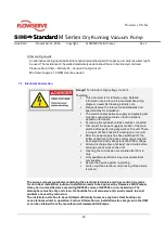
Purge control device causes that motor and electronics casing will be flushed and supplied with purge
gas [NFPA496]. After termination of the flushing process the power supply of the SIHIdry
electronics
[STE12 Board] is released by a signal contact. Then the pump is ready for operation.
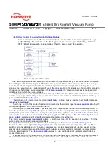
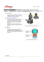
Figure 21: Operation Flow Chart
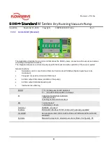
The starting signal can be activated by the control system or (optional) directly at the control panel of the pump.
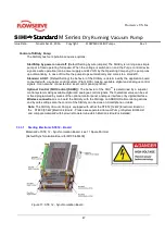
The unit begins with the rotor diagnosis. Then the center position of the mechanical gear is traced. Then during
operation the electronic gear causes that the mechanical gear never will be in engagement. During the rotor
diagnosis the output warning is selected and (if used) the corresponding light signal is switched on. After completing
the diagnosis, the SIHIdry system switches to the
Warm-up mode
; the ‘Operation’ message is displayed in all
conditions under which the pump operates.
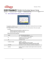
The pump remains in the Warm-up mode until the input 'Tmin' is active. The suction-side valve remains closed
and the pump is operated at a higher speed. Once the minimum temperature is reached (input 'Tmin' is active), the
pump switches to the
Standby mode
.
The connection of a temperature recording (
input Tmin
– optional) makes possible to set 2 different speeds
(
stand-by
and
warm up
).
The change from/to this mode of operation is initiated by the control signal
vacuum requirement
or by the
corresponding switch at the optional control panel.
Switching over to
vacuum mode
is possible only when the pump has reached a minimum temperature, i.e.
when the pump is warmed up. W hen the pump is rotating always the output operation is selected and (optional) the
corresponding indicator is switched on. During
vacuum mode
the pump follows the
set point value
and the suction
valve will be opened. The
vacuum mode
is the pumping phase of the pump; in this phase the
output vacuum
mode output
is selected and (if exists) the corresponding indicator is switched on.
The control signal
vacuum requirement
enables to switch over to
stand by
operation at any time. Then the
suction valve (optional) will be closed immediately.
The
input Tmin
does not have any influence when switching over from
vacuum mode
to
stand by mode
.
By means of the control signal
cleaning requirement
or (optional) the corresponding switch, it is possible to
switch over to the state cleaning. The pump is operated at a constant speed (solvent injecting speed) and the
solvent flushing valve will be opened. In this phase the output cleaning is selected or (optional) the corresponding
indicator is switched on. The
cleaning operation
serves to flush and to clean of the displacement rotors by
means of a solvent.
It is possible to stop the pump at any time with the aid of the input stop or (optional) the corresponding key of
the control panel. Hereby the pump is stopped immediately and (optional) the suction valve will be closed.
Summary of Contents for SIHI dry Standard H Series
Page 82: ......

