8
Flowserve US Inc.
SIHI
dry
dry
dry
dry
Standard
Standard
Standard
Standard M Series
Dry Running Vacuum Pump
Issue Date: November 21, 2016 Copyright:
FLOWSERVE SIHI Pumps Rev 1
List of Figures
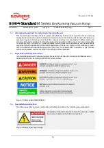
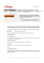
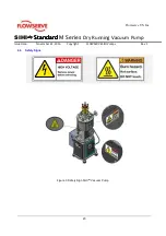
Figure 1: Safety Labels [ANSI Z535.6] ........................................................................................................... 10
Figure 2: Safety Label High Voltage .............................................................................................................. 10
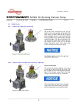
Figure 3: Safety Sign SIHIdry
Vacuum Pump ................................................................................................. 20
Figure 4: Strainer Insert [Sieve] ..................................................................................................................... 22
Figure 5: Suction Check Valve ....................................................................................................................... 22
Figure 6: Section Cut SIHIdry
M - Model ........................................................................................................ 24
Figure 7a: STE12 Electronic Board ............................................................................................................... 25
Figure 8: Cooling Principle ............................................................................................................................. 26
Figure 9: Shaft Seal Principle ........................................................................................................................ 27
Figure 10: Piston Ring Purge ......................................................................................................................... 27
Figure 11: Purge Gas Control Unit ................................................................................................................. 28
Figure 12: Capacity Curve for M - Series ....................................................................................................... 32
Figure 13: Example Center Of Gravity [Crate] ................................................................................................ 34
Figure 14: Flange Force & Torque Process Connection ................................................................................. 39
Figure 15: Flange Force & Torque Cooling Connection .................................................................................. 39
Figure 16: Electronic Housing ........................................................................................................................ 46
Figure 17: STE12 Synchronization Board ....................................................................................................... 47
Figure 18: Example Electrical Connection [Safety Chain] ............................................................................... 51
Figure 19: Operating Indicators ..................................................................................................................... 56
Figure 20: Expo Purge Gas Control Unit ........................................................................................................ 58
Figure 21: Operation Flow Chart .................................................................................................................... 59
Figure 22: Suction Sieve & Purge Gas Unit.................................................................................................... 63
Figure 23: Bearing Arrangement .................................................................................................................... 63
Figure 24: Overview of Gas kits & O-Rings .................................................................................................... 64
Figure 25: SIHIdry
Rotors .............................................................................................................................. 65
Figure 26: Removal of suction cover .............................................................................................................. 67
Figure 27: Pulling of pump chamber .............................................................................................................. 68
Figure 28: Removal of suction cover…………………………………. ................................................................ 68
Figure 29: Removal of cooling inlet tube…………………………………. .......................................................... 69
Figure 30: Removal of cooling coil unit …………………………………. ........................................................... 69
Figure 31: Disassembly cooling coil…………………………………. ................................................................. 69
Figure 32: Assembling of the cooling coil ....................................................................................................... 72
Figure 33: Assembling of the cooling cover .................................................................................................... 72
Figure 34: Assembling of the cooling inlet tube …………………………………. ............................................... 72
Figure 35: Assembling of the pump chamber ................................................................................................ 73
Figure 36: Assembling suction flange ............................................................................................................. 58
Summary of Contents for SIHI dry Standard H Series
Page 82: ......


