73
Flowserve US Inc.
SIHI
dry
dry
dry
dry
Standard
Standard
Standard
Standard M Series
Dry Running Vacuum Pump
Issue Date: November 21, 2016 Copyright:
FLOWSERVE SIHI Pumps Rev 1
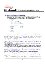
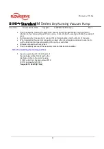
1. Apply vacuum grease to a new O-ring (41.22)
and insert in the intended slot in the upper
flanged surface of the motor housing (10.40).
2. Insert two new cylindrical pins (56.20) in the
holes in the upper flanged surface of the motor
housing (10.40).
4. Screw in two clevises (c) opposite each other with
an appropriate screw in each of the free threaded
holes on the top side of the spindle pump housing
as far as possible. Then hook in a suitable
shackle in the clevis, attach the transporting
slings to the crane and carefully lower the spindle
pump housing using the crane.
5. Before the housing is set down on the flange of
the motor housing, ensure that the two
cylindrical pins in the motor housing slide in the
intended holes on the underside of the spindle
pump housing.
6. Use the 12 hexagon screws M8 (90.11) to fix the
spindle pump housing (10.30) below the upper
flange of the motor housing (10.40).
Torque M8 (90.11): 18.5lb ft [25Nm]
7. Fix the union nut on the cooling hose to the
corresponding thread in the spindle pump
housing.
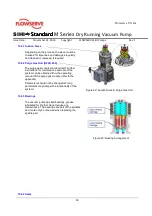
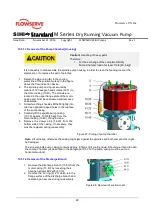
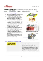
Figure 35: Assembling of the pump chamber
10.5.2.4 Assembling the Suction Cover Plate
1.
Apply vacuum grease to a new O-ring (41.20) and
insert in the top slot of the spindle pump housing
(10.30).
2.
Check the space above the spindles in the
housing for small parts, cloths, chips, etc.
3.
Place the suction cover (16.20) on the spindle pump
housing and secure by means of the 8 hexagon
screws M10 (90.12).
Torque M10 (90.12): 37lb ft [50Nm]
Figure 36: Assembling suction flange
Note: After the suction cover has been properly assembled, the opening of the suction orifice (ANSI 2” –
M100/160/250 ANSI 4” M400- must be closed by means of a suitable plug to protect the working area of the
pump from damaging bits. This plug may only be removed when the pump is installed in the system.
10.5.2.5 Assembling the Vacuum Pump in the System
1.
Assemble the vacuum and pressure lines as well as all add-on parts.
2.
Assemble all the temperature transmitters (if installed) on the pump housing.
3.
Assemble the cooling water inlet on the motor housing and cooling water outlet via the spindle
pump housing. Remove the plug from the cooling jacket, check the fill level of the coolant in the
housing and install the original plug.
4.
Complete further startup work in accordance with chapter 10 Installation of The SIHIdry Vacuum
Pump.
Summary of Contents for SIHI dry Standard H Series
Page 82: ......

