WIK USER INSTRUCTIONS ENGLISH BO2662 5/09
Page 12 of 76
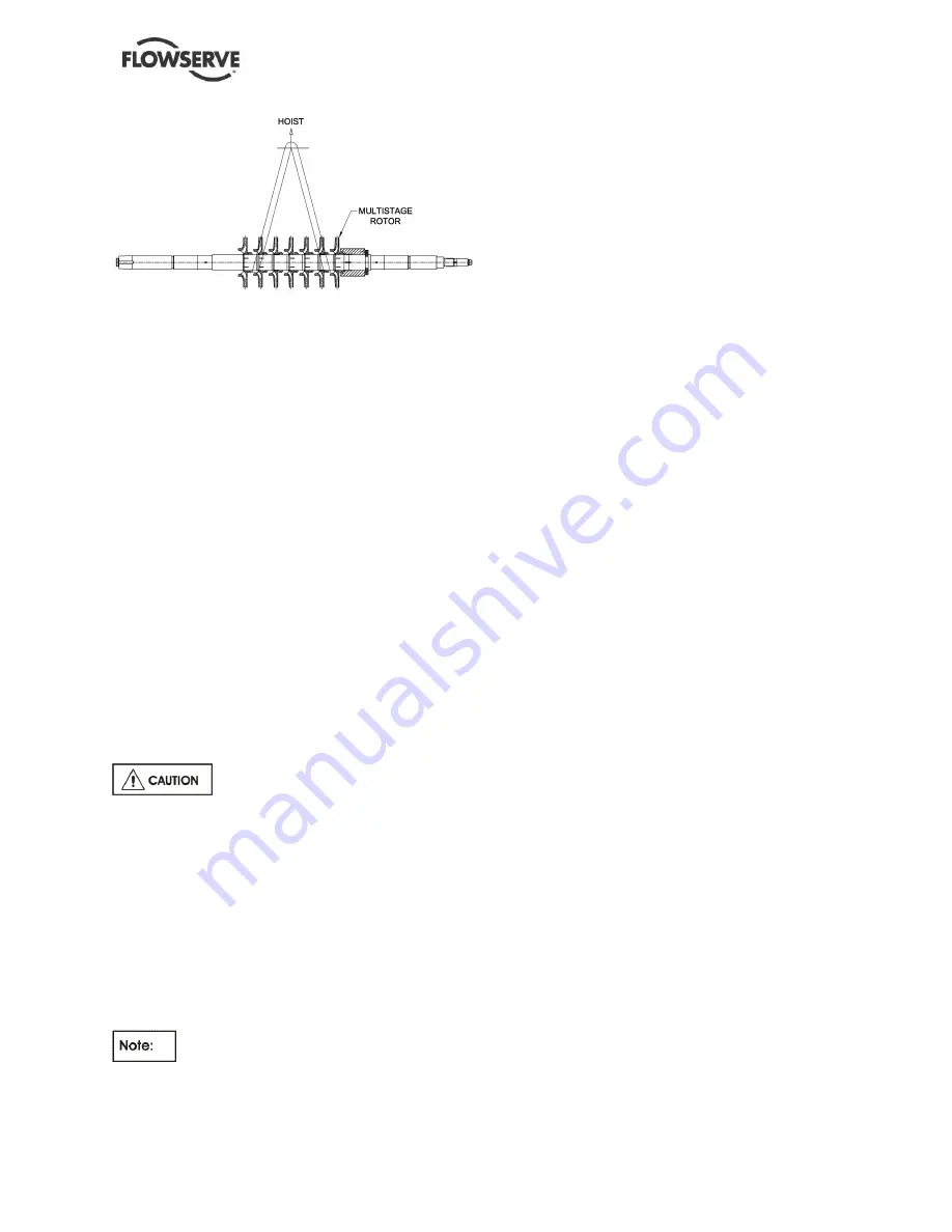
Figure 2- 4: Rotor Lifting Points
3) Adhere to the following task outline for uncrating
and subsequent handling of the rotor:
a) Remove sides and ends of box.
b) Remove fastenings that hold rotor to box,
and then remove plastic cover.
c) Place a nylon strap or a soft cable around
sleeve spacer or impeller hub between first
and second impellers at each end of rotor
(see Rotor Lifting Points
Figure 2-4
).
d) Attach ends of nylon straps to hoist and
verify that hoist is over center of gravity: if
not, lower rotor and reposition strap on light
end between second and third impellers
(see Rotor Lifting Points
Figure 2-4
).
e) Lift rotor straight up and place it in a stable,
level location on supports from shipping box
(or their equivalent).
2.3.5 Multistage shaft
To lift the bare multistage shaft from the shipping
crate and for subsequent handling, proceed as
follows:
Lifting shaft by a single strap around
its middle or only one end will cause bending of
shaft.
1) Remove sides and ends of box; shaft must clear
box without binding.
2) Remove fastenings that hold shaft to box, and
then remove plastic cover.
3) Place nylon straps around shaft at points
indicated by factory-installed markers. If no
markers are present, measure 25 percent of
total shaft length from each end of shaft and
place nylon straps around shaft at these points.
The shaft should be stored on wood in an
indoor environment where the temperature does not
fall below 16°C (60°F), completely away from
sunlight, and at least 100 mm (4 in.) above floor.
4) Use spreader bar to hold straps in place, attach
hoist to center of bar, lift shaft, and place it:
a) Either on wood supports of equal height that
are not more than 600 mm (24 in.) apart and
no further than 425 mm (17 in.) from shaft
end
b) Or in vertical position which is within 10
degrees of the perpendicular to the horizon
2.4
Storage
This section provides storage data for pumps and
parts manufactured by Flowserve. Storage data for
drivers and other auxiliary equipment may be found
in section 10 of this manual.
2.4.1 Pump preservative standards
For domestic shipments the following standards,
consistent with those recommended by the
American Petroleum Institute for pumps, are applied:
1) All inner surfaces and internal parts of the pump
casings and bearing housings are fully coated
with a petroleum-based rust preventative, except
as follows:
a) If customer requires specific preservation,
these specifications will be met
b) Parts which are made of stainless steel are
never coated
c) Internal surfaces of pumps to be used in
boiler feed service are not coated, unless
the pump is to be stored for more than six
months, in which case any internal
components made of cast iron or carbon
steel will be coated.
2) External surfaces are coated with a paint that
combines a primer with a finish coat, unless
otherwise specified by contract.
3) External surfaces of components required to be
kept free of paint, such as the shaft and coupling,
are coated with a petroleum-based rust
preventative.
4) Glass surfaces such as gauge and indicator
faces are masked.
5) Flanged openings are protected by wood or
metal covers in accordance with the applicable
edition of API 610.
6) All openings beveled for welding are protected
by wood or metal covers attached and sealed
with adhesive tape.
7) All threaded openings in the piping, pump casing,
and auxiliary equipment are closed with
threaded pipe plugs made of metal and suitable
for permanent use.
For international shipments, crating and preservative
measures are provided as specified by contract.


